MAX32665-MAX32668 User Guide
Maxim Integrated Page 257 of 457
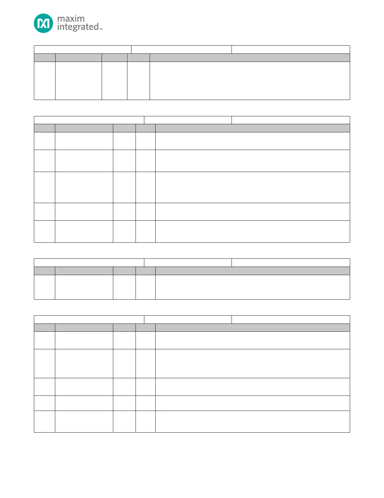
Start ADC Conversion
Write this bit to 1 to start an ADC conversion. When the conversion is complete, the
hardware automatically sets this bit to 0 indicating the conversion is complete.
0: ADC inactive or data conversion complete.
1: Start ADC conversion and remains set until complete.
Table 11-7: ADC Status Register
Reserved for Future Use
Do not modify this field.
ADC Overflow Flag
0: No overflow on last conversion
1: Overflow on last conversion
ADC Power-Up State
This field is set to 1 when the ADC charge pump is powering up.
0: AFE is not in power-up delay.
1: AFE is currently in the power-up delay state.
Reserved for Future Use
Do not modify this field.
ADC Conversion in Progress
0: ADC is idle
1: ADC conversion is in progress
Table 11-8: ADC Data Register
ADC Data
This field contains the ADC conversion output data. See the Data Conversion Output
Alignment for details.
Table 11-9: ADC Interrupt Control Register
Reserved for Future Use
Do not modify this field.
ADC Interrupt Pending
0: No ADC interrupt pending.
1: At least one ADC interrupt is pending, and the corresponding interrupt enable
bit is set.
Reserved for Future Use
Do not modify this field.
ADC Overflow Interrupt Flag
1: The last conversion resulted in an overflow
ADC Low Limit Interrupt Flag
1: The last conversion resulted in a low-limit condition for one of the limit
registers.