MAX32665-MAX32668 User Guide
Maxim Integrated Page 389 of 457
If the system clock is set to 120MHz,
, the OWM_CLK_DIV_1US.divisor field should be set to 60 as shown in
Equation 20-2.
Equation 20-2: OWM Clock Divisor for
20.3 1-Wire Protocol
The general timing and communication protocols used by the OWM interface are those standardized for the 1-Wire
network.
Because the 1-Wire interface is a master interface, it initiates and times all communication on the 1-Wire bus. Except for
the present pulse generation when a device first connects to the 1-Wire bus, 1-Wire slave devices complete 1-Wire bus
communication only as directed by the 1-Wire bus master. From a firmware perspective, the lowest-level timing and
electrical details of how the 1-Wire network operates are unimportant. The application can configure the OWM module
properly and direct it to complete low-level operations such as reset, read, and write bit/byte operations. Thus, the OWM
module on the microcontroller is designed to interface to the 1-Wire bus at a low level.
20.3.1 Networking Layers
In the Book of iButton Standards, the 1-Wire communication protocol is described in terms of the ISO-OSI model
(International Organization of Standardization (ISO) Open System Interconnection (OSI) network layer model). Network
layers that apply to this description are the Physical, Link, Network, and Transport layers. The Presentation layer would
correspond to higher-level application software functions (such as library layers) that implement communication protocols
using the 1-Wire layers as a foundation.
20.3.1.1 Bus Interface (Physical Layer)
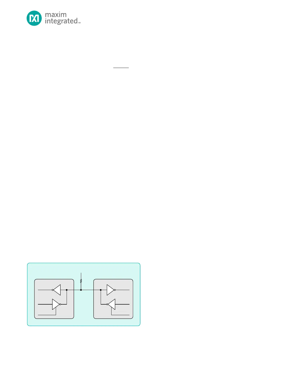
The 1-Wire communication bus consists of a single data/power line plus ground. devices (either master or slave) that
interface to the 1-Wire communication bus using an open-drain (active low) connection, which means that the 1-Wire bus
normally idles in a high state.
An external pullup resistor is used to pull the 1-Wire line high when no master or slave device is driving the line. This means
that 1-Wire devices do not actively drive the 1-Wire line high. Instead, they either drive the line low or release it (set their
output to high impedance) to allow the external resistor to pull the line high. This allows the 1-Wire bus to operate in a
wired-AND manner as shown in Figure 20-1 and avoids bus contention if more than one device attempts to drive the 1-Wire
bus at the same time.
Figure 20-1: 1-Wire Signal Interface