MAX32665-MAX32668 User Guide
Maxim Integrated Page 345 of 457
Equation 16-11: Capture Mode Elapsed Time
16.12 Timer Registers
Address offsets for the timer registers are shown in Table 16-1. Register fields marked as Reserved for Future Use should
not be modified. All Timer instances contain an identical set of registers. Register names for a specific instance are defined
by appending the instance number to the peripheral name. For example, the Timer Count Register for Timer 0 is TMR0_CNT
while the Timer Count Register for Timer 1 is TMR1_CNT, etc.
See Table 3-1: APB Peripheral Base Address Map for the Timer 0 (TMR0_) to Timer 5 (TMR5_) Peripheral Base Addresses.
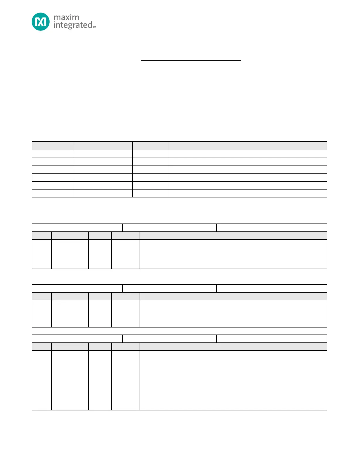
Table 16-1: Timer Register Offset, Names, Access and Descriptions
Timer Non-Overlapping Compare Register
Table 16-2: Timer Count Registers
Timer Count Value
The current count value for the timer. This field increments as the timer counts. Reads
of this register are always valid. Prior to writing this field, disable the timer by clearing
bit TMRn_CN.ten.
Table 16-3: Timer Compare Registers
Timer Compare Value
The value in this register is used as the compare value for the timer’s count value. The
compare field meaning is determined by the specific mode of the timer. See the timer
mode’s detailed configuration section for compare usage and meaning.
Timer PWM Match
In PWM mode, this field sets the count value for the first transition period of the
PWM cycle. At the end of the cycle where TMRn_CNT equals TMRn_CMP, the PWM
output transitions to the second period of the PWM cycle. The second PWM period
count is stored in the TMRn_CMP register. The value set for TMRn_PWM.pwm must
be less than the value set in TMRn_CMP for PWM mode operation.
Timer Capture Value
In Capture, Compare, and Capture/Compare modes, this field is used to store the
TMRn_CNT value when a Capture, Compare, or Capture/Compare event occurs.