23-2
Cisco ONS 15454 DWDM Installation and Operations Guide, R6.0
August 2005
Chapter 23 Alarm Management Reference
23.2 Alarm Counts on the LCD for a Node, Slot, or Port
23.2 Alarm Counts on the LCD for a Node, Slot, or Port
You can view node, slot, or port-level alarm counts and summaries using the buttons on the ONS 15454
LCD panel. The Slot and Port buttons toggle between display types; the Slot button toggles between
node display and slot display, and the Port button toggles between slot and port views. Pressing the
Status button after you choose the display mode changes the display from alarm count to alarm summary.
The ONS 15454 has a one-button update for some commonly viewed alarm counts. If you press the Slot
button once and then wait eight seconds, the display automatically changes from a slot alarm count to a
slot alarm summary. If you press the Port button to toggle to port-level display, you can use the Port
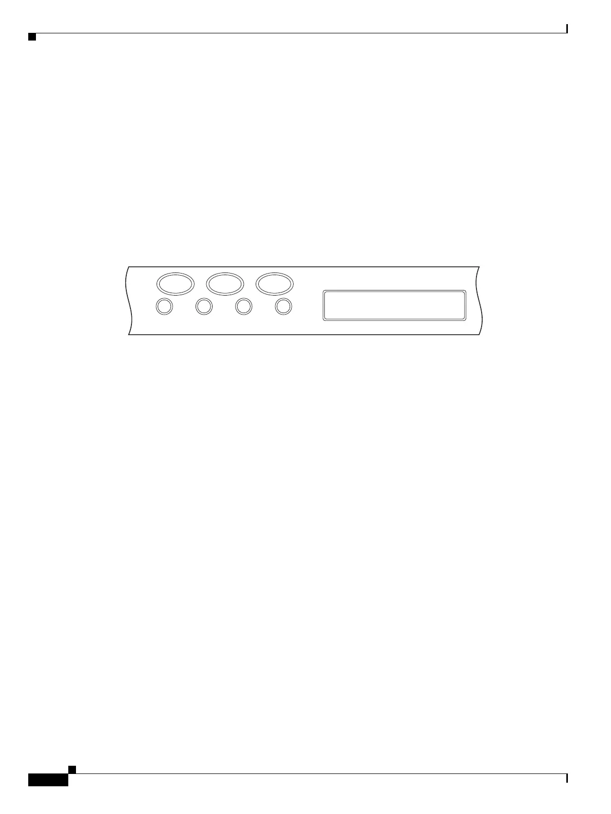
button to toggle to a specific slot and to view each port’s port-level alarm count. Figure 23-1 shows the
LCD panel layout.
Figure 23-1 Shelf LCD Panel
23.3 Alarm Display
In the card, node, or network CTC view, click the Alarms tab to display the alarms for that card, node,
or network. The Alarms window shows alarms in compliance with Telcordia GR-253-CORE. This means
that if a network problem causes two alarms, such as loss of frame (LOF) and loss of signal (LOS), CTC
only shows the LOS alarm in this window because it supersedes the LOF and replaces it.
The Path Width column in the Alarms and Conditions tabs expands on the alarmed object information
contained in the access identifier (AID) string (such as “STS-4-1-3”) by giving the number of STSs
contained in the alarmed path. For example, the Path Width tells you whether a critical alarm applies to
an STS1 or an STS48c. The column reports the width as a 1, 3, 6, 12, 48, etc. as appropriate, understood
to be “STS-N.”
Table 8-1 on page 8-6 lists the column headings and the information recorded in each column and
Table 8-2 on page 8-7 provides the color codes for alarm and condition severities.
For a list of circuits with raised alarms, see the “NTP-G66 View Alarm-Affected Circuits” procedure on
page 8-14.
23.3.1 Viewing Alarms by Time Zone
By default, alarms and conditions are displayed with the time stamp of the CTC workstation where you
are viewing them. However, you can set the node to report alarms (and conditions) using the time zone
where the node is located. See the “DLP-G118 Display Alarms and Conditions Using Time Zone” task
on page 8-11 for instructions.
FAN FAIL
Slot
8/18/03
04.06-002L-10
24˚C
97758
CRIT MAJ MIN
Status Port

 Loading...


