3-49
Cisco ONS 15454 DWDM Installation and Operations Guide, R6.0
September 2005
Chapter 3 Turn Up a Node
NTP-G34 Install Fiber-Optic Cables on DWDM Cards and DCUs
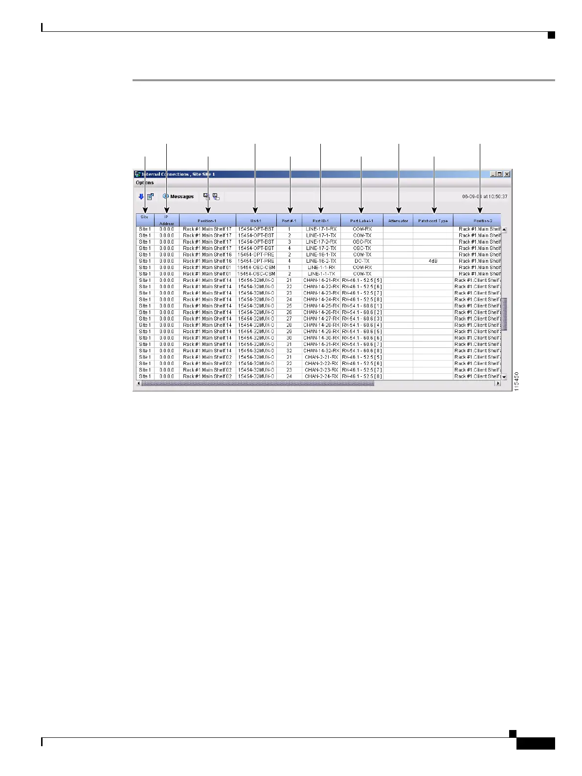
Step 1 View the Cisco MetroPlanner Internal Connections table. Figure 3-9 shows an example.
Figure 3-9 Cisco MetroPlanner Internal Connections Table
Step 2
Review the Cisco MetroPlanner Internal Connections table for the node that you are provisioning. The
table identifies the patchcords that you must cable by their endpoints. Position 1 identifies the fiber start
point; Position 2 indicates the fiber endpoint. The patchcord endpoints are identified by site, slot, and
port. Information provided by the Internal Connections table includes:
• Site—The DWDM network site number for the node where you are provisioning the internal
connections.
• IP Address—The node IP address.
• Position-1—The first position rack, shelf, and slot. For example, Rack#1.Main Shelf.02 refers to
Slot 2 in the main shelf of Rack 1. Refer to the Cisco MetroPlanner Site Dialog window for rack and
shelf names and locations.
• Unit-1—The ONS 15454 DWDM card (unit) that is installed in the first position slot.
• Port#-1—The port identifier shown in the CTC for the first Position-1 connection.
• Port ID-1—The port identifier shown in TL1 for the Position-1 connection.
• Port Label-1—The name of the physical port printed on the card’s front plate and shown in CTC
card view for the Position-1 connection.
• Attenuator—Indicates whether attenuation is required.
• Patchcord Type—Indicates the level of attenuation that is required, if needed.
• Position-2—The second position rack, shelf, and slot. For example, Rack#1.Main Shelf.02 refers to
Slot 2 in the main shelf of Rack 1. Refer to the Cisco MetroPlanner Site Dialog window for rack and
shelf names and locations.
Site Position-1 Port#-1
IP Address Unit-1
Port Label-1 Patchcord Type
Port ID-1 Attenuator Position-2

 Loading...


