15-15
Cisco ONS 15454 DWDM Installation and Operations Guide, R6.0
September 2005
Chapter 15 Shelf Hardware Reference
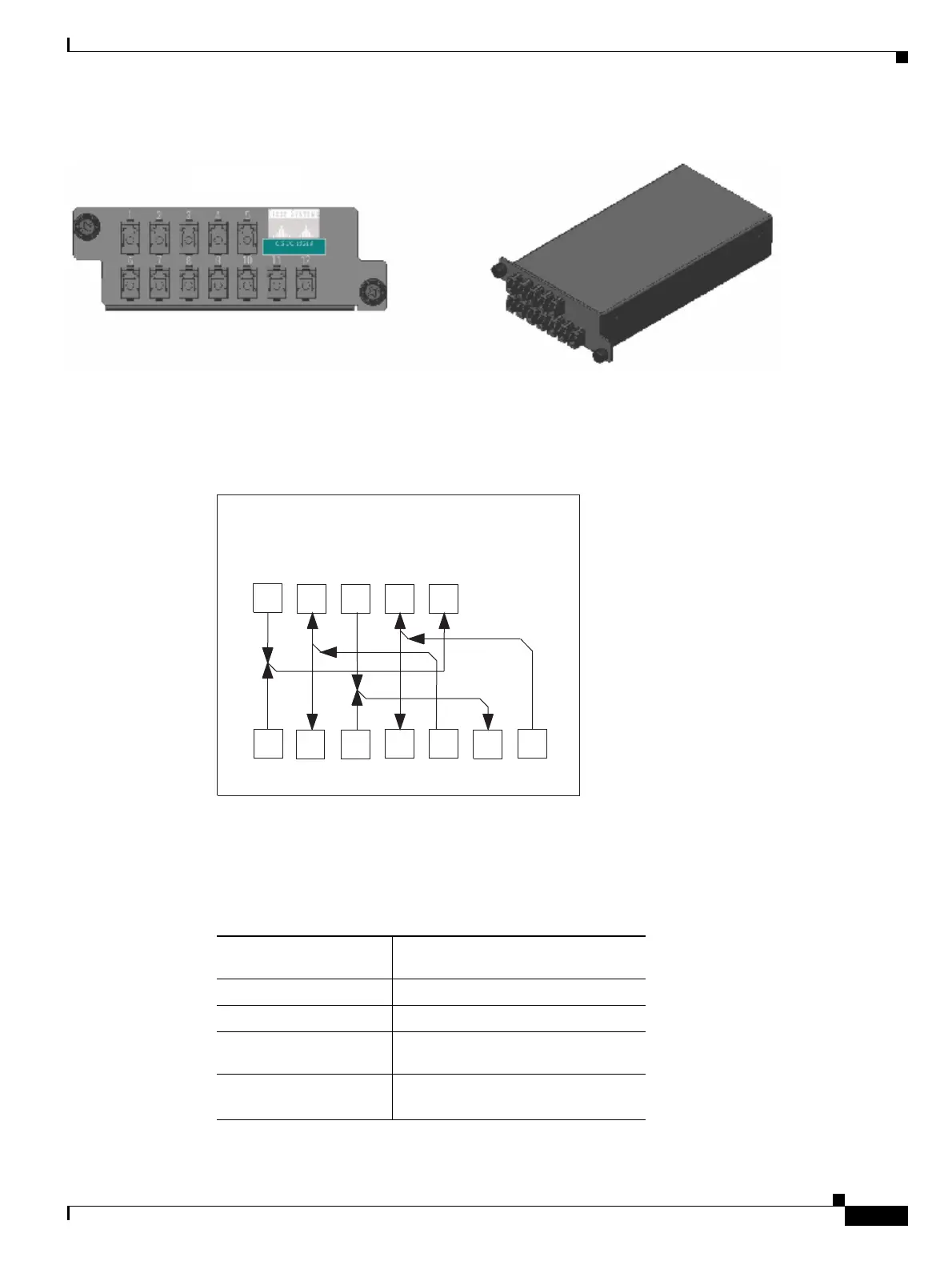
15.4.2 Y-Cable Protection Module
Figure 15-13 ONS 15454 Y-Cable Protection FlexLayer Module (Multimode)
Figure 15-14 shows how the module front panel ports are mapped and labeled. The multimode module
is mapped and labeled the same as the single-mode module.
Figure 15-14 Y-Cable Protection Component Connector Mapping and Labeling
Table 15-2 details the single-mode and multimode front panel Protection A mapping. It shows how two
DWDM receive inputs (client working and protect) provide one output signal to the customer client
equipment, using the module combiner function.
Front Panel
CS-MM-Y
90940
1:2 Splitter and 2:1 Combiner 15216-CS-MM/SM-Y
7 8
TXa2
RXb2
9
TXb2
12
RXb
2 3 4
TXa1
RXb1 TXb1
6
RXa2
1
RXa1
10
RXa
5
TXa
11
TXb
90941
Table 15-2 Protection A (TXP Cards 1 and 2) Port Mapping: Combiner from DWDM
Receive Port on the
Y-Cable Module
Signal Sources
1 (RXa1) Client TX port on the TXP 1 card
6 (RXa2) Client TX port on the TXP 2 card
Transmit Port on the
Y-Cable Module
Signal Destination
5 (TXa) RX port on customer client
equipment A

 Loading...


