18-29
Cisco ONS 15454 DWDM Installation and Operations Guide, R6.0
August 2005
Chapter 18 Network Reference
18.8.1 Gain Tilt Control at the Card Level
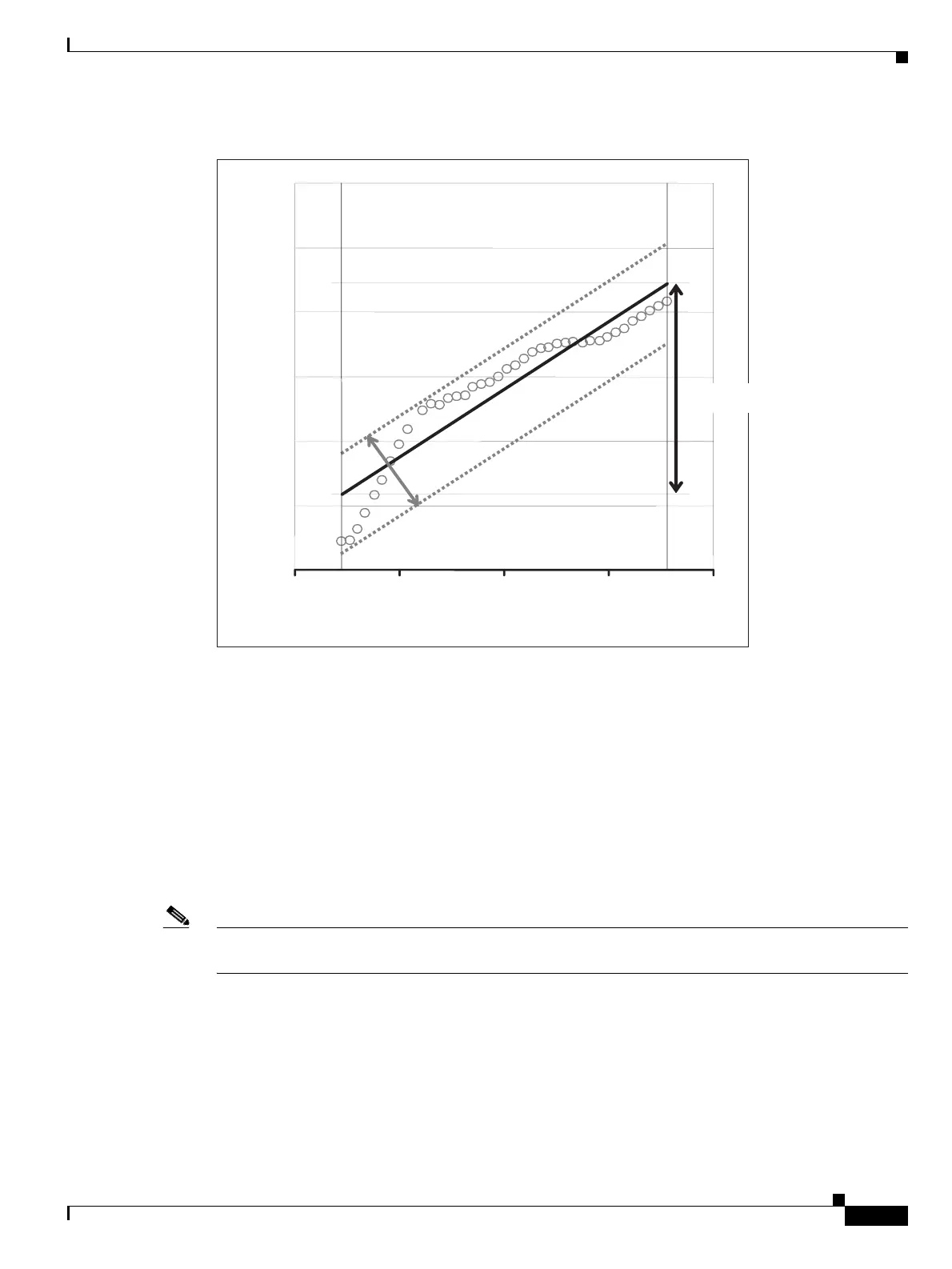
Figure 18-13 Effect of Gain Ripple and Gain Tilt on Amplifier Output Power
Gain ripple and gain tilt are defined as follows:
• Gain Ripple is random and depends on the spectral shape of the amplifier optical components.
• Gain Tilt is systematic and depends on the gain setpoint (Gstp) of the optical amplifier, which is a
mathematical function F(Gstp) that relates to the internal amplifier design.
Gain tilt is the only contribution to the power spectrum disequalization that can be compensated at the
card level. A Variable Optical Attenuator (VOA) internal to the amplifier can be used to compensate for
gain tilt.
An Optical Spectrum Analyzer (OSA) device is used to acquire the output power spectrum of an
amplifier. The OSA shows the peak-to-peak difference between the maximum and minimum power
levels, and takes into account the contributions of both gain tilt and gain ripple.
Note Peak-to-peak power acquisition using an OSA cannot be used to “measure” the Gain Tilt, because gain
ripple itself is a component of the actual measurement.
18.8.1 Gain Tilt Control at the Card Level
The OPT-BST/OPT-BST-E and OPT-PRE amplifier cards have a “flat” output (gain tilt = 0 dB) for only
a specific gain value (Gdesign), based on the internal optical design (see Figure 18-14).
-4
-2
0
2
4
1530.3 1560.6
Wavelength [nm]
Gain Tilt
Amplifier Output Spectrum
1550
Gain Ripple
Per-Channel power [dB]
134393

 Loading...


