16-58
Cisco ONS 15454 DWDM Installation and Operations Guide, R6.0
April 2006
Chapter 16 Card Reference
16.6.4 4MD-xx.x Card
VOAs are present in every input path of the multiplex section in order to regulate the optical power of
each multiplexed channel. Some optical input and output ports are monitored by means of photodiodes
implemented both for power control and for safety purposes. An internal control manages VOA settings
and functionality as well as photodiode detection and alarm thresholds. The power at the main output
and input ports is monitored through the use of virtual photodiodes. A virtual photodiode is implemented
in the firmware of the plug-in module. This firmware calculates the power on a port, summing the
measured values from all single channel ports (and applying the proper path insertion loss) and then
providing the TCC2/TCC2P card with the obtained value.
16.6.4.1 Wavelength Pairs
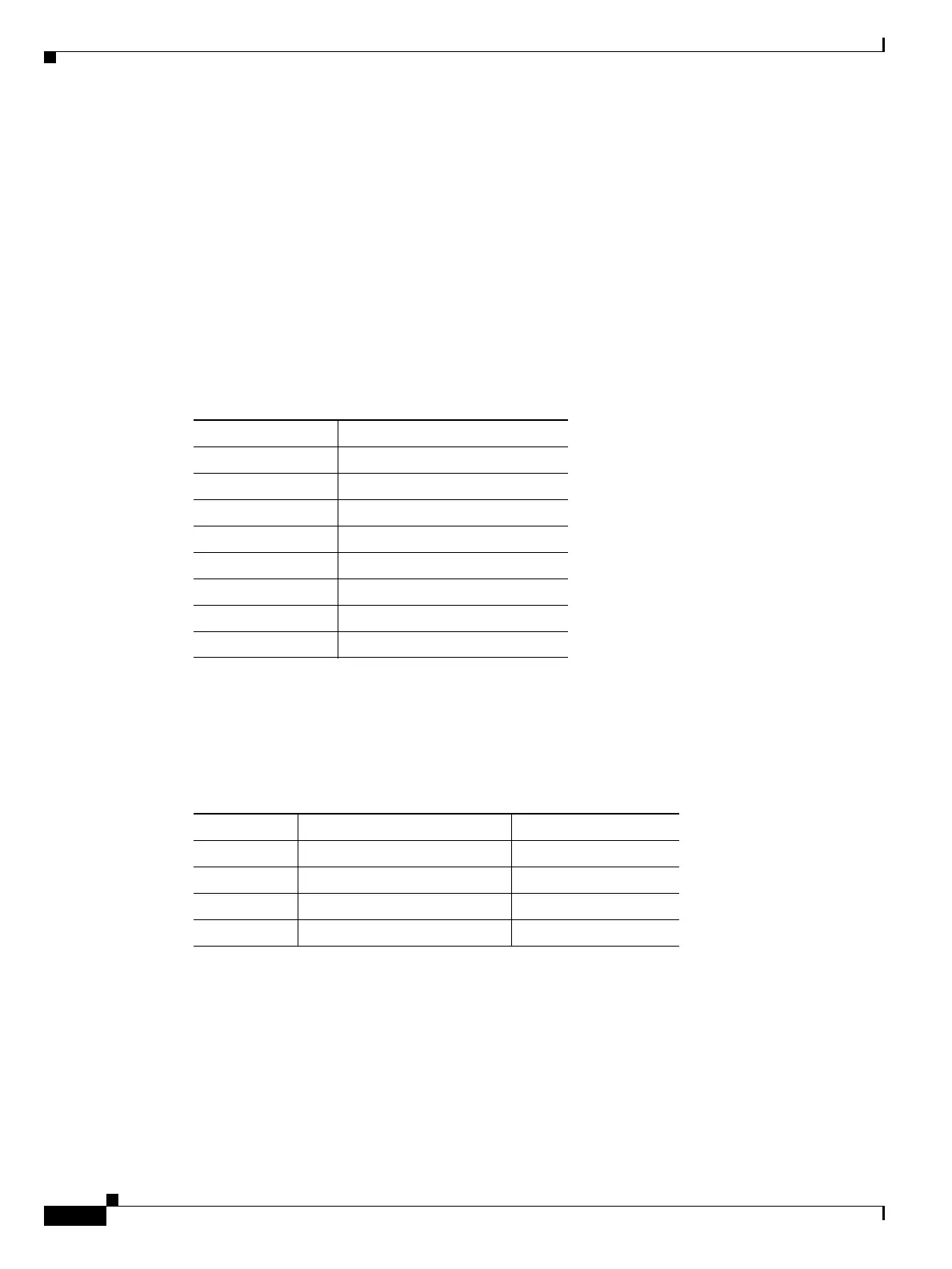
Table 16-33 shows the band IDs and the add/drop channel IDs for the 4MD-xx.x card.
16.6.4.2 Power Monitoring
Physical photodiodes P1 through P8 and virtual photodiodes V1 and V2 monitor the power for the
4MD-xx.x card. The returned power level values are calibrated to the ports as shown in Table 16-34.
16.6.4.3 4MD-xx.x Card-Level Indicators
The 4MD-xx.x card has three card-level LED indicators, described in Table 16-35.
Table 16-33 4MD-xx.x Channel Sets
Band ID Add/Drop Channel IDs
Band 30.3 (A) 30.3, 31.2, 31.9, 32.6
Band 34.2 (B) 34.2, 35.0, 35.8, 36.6
Band 38.1 (C) 38.1, 38.9, 39.7, 40.5
Band 42.1 (D) 42.1, 42.9, 43.7, 44.5
Band 46.1 (E) 46.1, 46.9, 47.7, 48.5
Band 50.1 (F) 50.1, 50.9, 51.7, 52.5
Band 54.1 (G) 54.1, 54.9, 55.7, 56.5
Band 58.1 (H) 58.1, 58.9, 59.7, 60.6
Table 16-34 4MD-xx.x Port Calibration
Photodiode CTC Type Name Calibrated to Port
P1–P4 ADD COM TX
P5–P8 DROP DROP TX
V1 OUT COM COM TX
V2 IN COM COM RX

 Loading...


