16-29
Cisco ONS 15454 DWDM Installation and Operations Guide, R6.0
April 2006
Chapter 16 Card Reference
16.4.2 OSC-CSM Card
16.4.1.2 OSCM Card-Level Indicators
The OSCM card has three card-level LED indicators, described in Table 16-17.
16.4.1.3 OSCM Port-Level Indicators
You can find the status of the card ports using the LCD screen on the ONS 15454 fan-tray assembly. Use
the LCD to view the status of any port or card slot; the screen displays the number and severity of alarms
for a given port or slot. The OSCM has one OC-3/STM-1 optical port located on the faceplate. One
long-reach OSC transmits and receives the OSC to and from another DWDM node. Both data
communications network (DCN) data and FE payload are carried on this link.
16.4.2 OSC-CSM Card
The OSC-CSM card is used in unamplified nodes. This means that the booster amplifier with the OSC
wavelength combiner and separator is not required for OSC-CSM operation. The OSC-CSM can be
installed in Slots 1 to 6 and 12 to 17. To operate in hybrid mode, the OSC-CSM cards must be
accompanied by cross-connect cards. The cross-connect cards enable functionality on the OC-N/STM-N
cards and electrical cards.
The OSC-CSM supports the following features:
• Optical combiner and separator module for multiplexing and demultiplexing the optical service
channel to or from the wavelength division multiplexing (WDM) signal
• OC-3/STM-1 formatted OSC
• SDC forwarded to the TCC2/TCC2P cards for processing
• Distribution of the synchronous clock to all nodes in the ring
• 100BaseT FE UDC
• Monitoring functions such as orderwire support
• Optical safety: Signal loss detection and alarming, fast transmitted power shut down by means of an
optical 1x1 switch
• Optical safety remote interlock (OSRI), a feature capable of shutting down the optical output power
• Automatic laser shutdown (ALS), a safety mechanism used in the event of a fiber cut
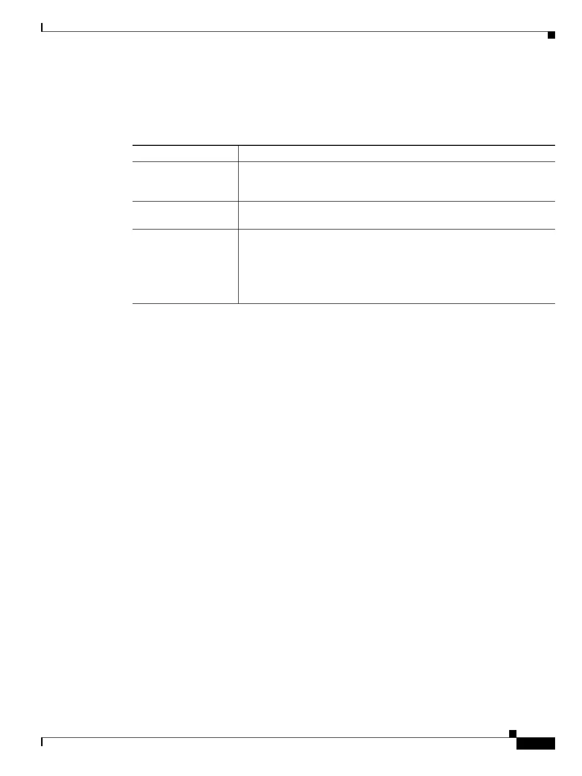
Table 16-17 OSCM Card-Level Indicators
Card-Level Indicators Description
Red FAIL LED The red FAIL LED indicates that the card’s processor is not ready or that
there is an internal hardware failure. Replace the card if the red FAIL LED
persists.
Green ACT LED The green ACT LED indicates that the OSCM is carrying traffic or is
traffic-ready.
Amber SF LED The amber SF LED indicates a signal failure or condition such as loss of
signal (LOS), loss of frame alignment (LOF), line alarm indication signal
(AIS-L), or high BER on one or more of the card’s ports. The amber signal
fail (SF) LED also illuminates when the transmit and receive fibers are
incorrectly connected. When the fibers are properly connected, the light
turns off.

 Loading...


