16-65
Cisco ONS 15454 DWDM Installation and Operations Guide, R6.0
April 2006
Chapter 16 Card Reference
16.7.2 AD-2C-xx.x Card
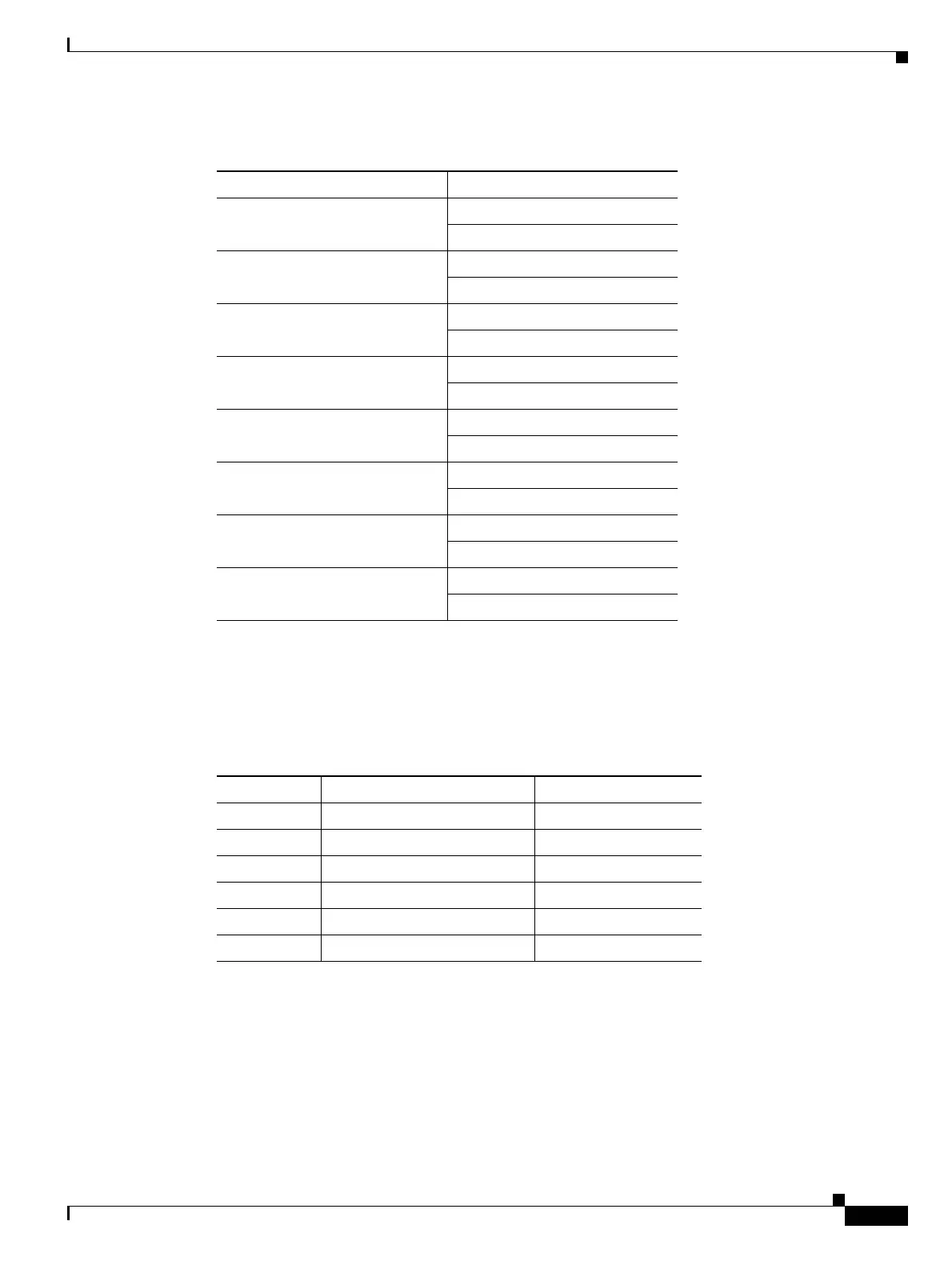
16.7.2.2 Power Monitoring
Physical photodiodes P1 through P10, and virtual photodiodes V1 and V2 monitor the power for the
AD-2C-xx.x card. The returned power level values are calibrated to the ports as shown in Table 16-39.
16.7.2.3 AD-2C-xx.x Card-Level Indicators
The AD-2C-xx.x card has three card-level LED indicators, described in Table 16-40.
Table 16-38 AD-2C-xx.x Channel Pairs
Band ID Add/Drop Channel ID
Band 30.3 (A) 30.3, 31.2
31.9, 32.6
Band 34.2 (B) 34.2, 35.0
35.8, 36.6
Band 38.1 (C) 38.1, 38.9
39.7, 40.5
Band 42.1 (D) 42.1, 42.9
43.7, 44.5
Band 46.1 (E) 46.1, 46.9
47.7, 48.5
Band 50.1 (F) 50.1, 50.9
51.7, 52.5
Band 54.1 (G) 54.1, 54.9
55.7, 56.5
Band 58.1 (H) 58.1, 58.9
59.7, 60.6
Table 16-39 AD-2C-xx.x Port Calibration
Photodiode CTC Type Name Calibrated to Port
P1–P4 ADD COM TX
P5–P8 DROP DROP TX
P9 IN EXP EXP RX
P10 OUT EXP EXP TX
V1 IN COM COM RX
V2 OUT COM COM TX

 Loading...


