Chapter 12
Tunneling and VPNs
RUGGEDCOM ROX II
CLI User Guide
376 Creating an L2TPv3 Tunnel
l2t-1-2
switch.0002
switch.0003
switch.0002
switch.0003
192.168.10.110
192.168.11.110 192.168.11.130
192.168.10.130
R1 R2
l2t-1-1
Figure16:Multiple LAN Extensions Over a Single L2TPv3 Tunnel
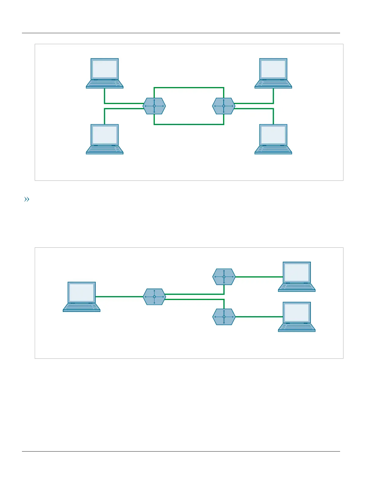
Multiple L2TPv3 Tunnels
In the following topology, two L2TPv3 tunnels are configured: one from router R1 to R2, and another from R1 to
R3. Each is converted to a bridge by the switch.0002 virtual switch.
Traffic sent from 192.158.10.110 to 192.168.10.130 traverses the l2t-1-1 bridge, and vice versa.
Traffic sent from 192.158.10.110 to 192.168.11.110 traverses the l2t-2-1 bridge, and vice versa.
switch.0002
R1
l2t-1-1
l2t-2-1
Figure17:Multiple LAN Extensions Over Multiple L2TPv3 Tunnels
Section12.4.2
Creating an L2TPv3 Tunnel
To create an L2TPv3 tunnel with another Provider Edge (PE) device, do the following:
1. Create the L2TPv3 Tunnel Interface
An L2TPv3 tunnel interface is created automatically by RUGGEDCOM ROX II whenever a session is defined.
The interface is listed under ip in the menu and adheres to the following naming convention: