According to the toner density measured by this sensor, the proper amount of toner is supplied to the
developer.
A counter corresponding to the frequency is used as the unit of TD sensor output. Thus, unlike a HST
sensor which directly detects Vt, the TD sensor output is converted into Vt for toner supply control.
In the TD sensor, there is an ID chip storing the machine identification information, the running distance
information of development unit and PCU, and other information used by image density control.
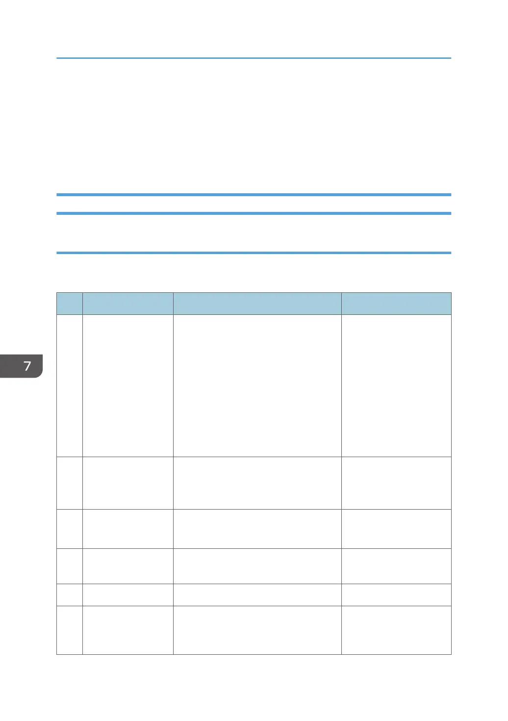
Process Control
Outline
Process control adjusts the condition of the imaging hardware to maintain a constant image density.
Process control is executed at the following times.
Process Control Operative Condition Related SPs
1
PowerON
ProCon :Set
When a certain time has passed after the
previous job end
(Except when recovering from an SC or
jam)
SP3-530-001
SP3-530-002
SP3-530-003
SP3-530-004
SP3-530-005
SP3-530-006
SP3-530-007
SP3-530-008
2 JobEnd ProCon :Set
When the value of the job end counter
becomes more than the threshold
(At job end)
SP3-534-001 to 004
SP3-534-011 to 014
3 Interrupt ProCon :Set
When the value of the job interrupt
counter becomes more than the threshold
SP3-533-001 to 004
SP3-533-011 to 014
4
Non-useTime
Procon :Set
When the value of the non-use time
counter becomes more than the threshold
SP3-531-001 to 004
5 Manual ProCon :Exe When SP 3-011 is used SP3-011-001 to 005
6 Toner End Recovery
After the Toner End Status is cleared
(Recovery is NOT done in the near end
status)
-
7. Detailed Descriptions
1120