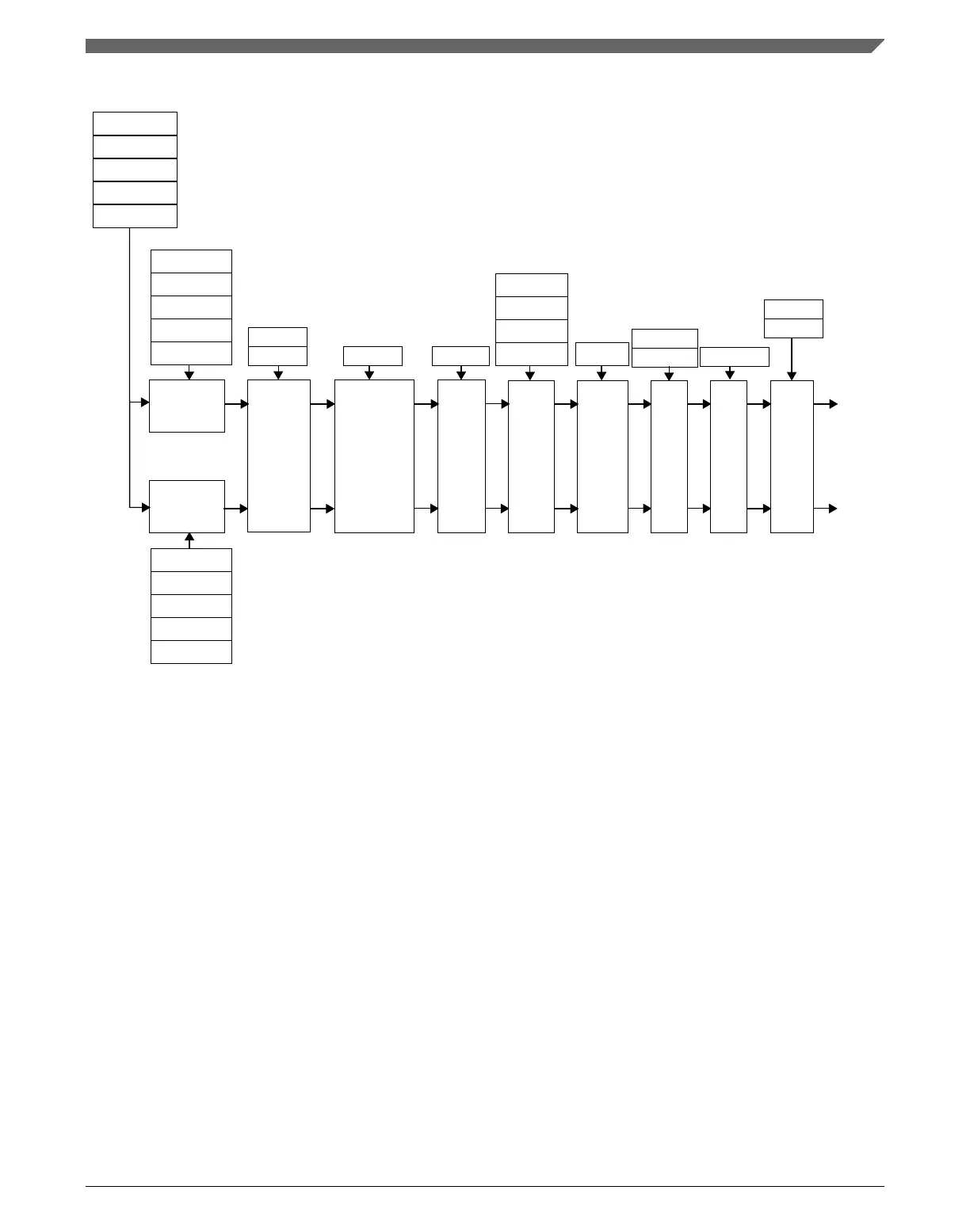
NOTE
The channels (n) and (n+1) are in output compare, EPWM, CPWM or combine modes.
pair channels (m) - channels (n) and (n+1)
initialization
complementary
mode
inverting
software
output
control
deadtime
insertion
output
mask
fault
control
polarity
control
FTM counter
QUADEN
DECAPEN
COMBINE(m)
CPWMS
C(n)V
MS(n)B
MS(n)A
ELS(n)B
ELS(n)A
generation of
channel (n)
output signal
generation of
channel (n+1)
output signal
C(n+1)V
MS(n+1)B
MS(n+1)A
ELS(n+1)B
ELS(n+1)A
channel
(n)
output
signal
channel
(n+1)
output
signal
CH(n)OI
CH(n+1)OI
COMP(m)
INV(m)EN
CH(n)OC
CH(n)OCV
CH(n+1)OC
CH(n+1)OCV
DTEN(m)
CH(n)OM
CH(n+1)OM
FAULTEN(m)
POL(n)
POL(n+1)
Figure 39-75. Priority of the features used at the generation of channels (n) and (n+1)
outputs signals
Note
The Initialization feature must not be used with Inverting and
Software output control features.
39.4.20
Channel trigger output
If CH(j)TRIG bit of the FTM External Trigger (FTM_EXTTRIG) register is set, where j
= 0, 1, 2, 3, 4, or 5, then the FTM generates a trigger when the channel (j) match occurs
(FTM counter = C(j)V).
The channel trigger output provides a trigger signal which has one FTM clock period
width and is used for on-chip modules.
Chapter 39 FlexTimer Module (FTM)
K22F Sub-Family Reference Manual, Rev. 4, 08/2016
NXP Semiconductors 1001

 Loading...