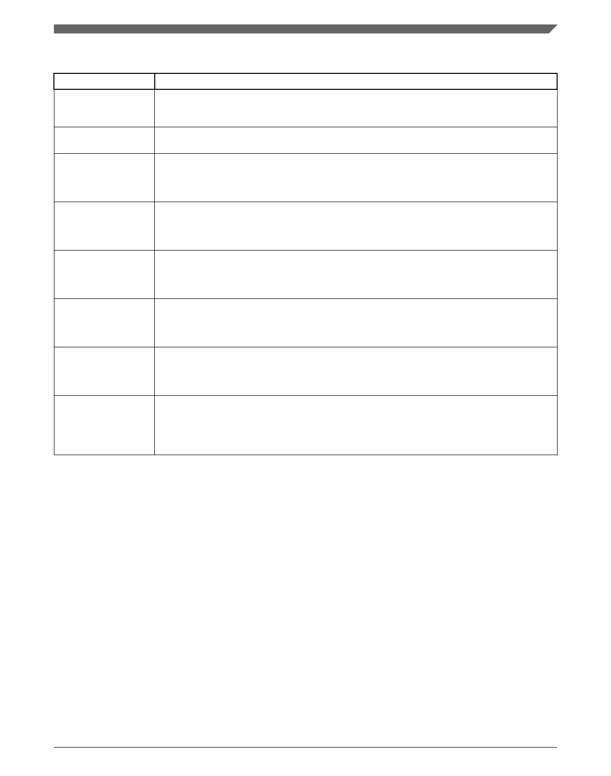
Table 15-1. Power modes (continued)
Mode Description
VLPW The core clock is gated off. The system, bus, and flash clocks continue to operate, although their
maximum frequency is restricted. See the Power Management chapter for details on the maximum
allowable frequencies.
VLPS The core clock is gated off. System clocks to other masters and bus clocks are gated off after all
stop acknowledge signals from supporting peripherals are valid.
LLS3 The core clock is gated off. System clocks to other masters and bus clocks are gated off after all
stop acknowledge signals from supporting peripherals are valid. The MCU is placed in a low
leakage mode by reducing the voltage to internal logic. All system RAM contents, internal logic and
I/O states are retained.
LLS2 The core clock is gated off. System clocks to other masters and bus clocks are gated off after all
stop acknowledge signals from supporting peripherals are valid. The MCU is placed in a low
leakage mode by reducing voltage to internal logicand powering down the system RAM2 partition.
The system RAM1 partition, internal logic and I/O states are retained.
1
VLLS3 The core clock is gated off. System clocks to other masters and bus clocks are gated off after all
stop acknowledge signals from supporting peripherals are valid. The MCU is placed in a low
leakage mode by powering down the internal logic. All system RAM contents are retained and I/O
states are held. Internal logic states are not retained.
VLLS2 The core clock is gated off. System clocks to other masters and bus clocks are gated off after all
stop acknowledge signals from supporting peripherals are valid. The MCU is placed in a low
leakage mode by powering down the internal logic and the system RAM2 partition. The system
RAM1 partition contents are retained in this mode. Internal logic states are not retained.
1
VLLS1 The core clock is gated off. System clocks to other masters and bus clocks are gated off after all
stop acknowledge signals from supporting peripherals are valid. The MCU is placed in a low
leakage mode by powering down the internal logic and all system RAM. I/O states are held. Internal
logic states are not retained.
VLLS0 The core clock is gated off. System clocks to other masters and bus clocks are gated off after all
stop acknowledge signals from supporting peripherals are valid. The MCU is placed in a low
leakage mode by powering down the internal logic and all system RAM. I/O states are held. Internal
logic states are not retained. The 1kHz LPO clock is disabled and the power on reset (POR) circuit
can be optionally enabled using STOPCTRL[PORPO].
1. See the devices' chip configuration details for the size and location of the system RAM partitions.
15.3 Memory map and register descriptions
Information about the registers related to the system mode controller can be found here.
Different SMC registers reset on different reset types. Each register's description provides
details. For more information about the types of reset on this chip, refer to the Reset
section details.
NOTE
The SMC registers can be written only in supervisor mode.
Write accesses in user mode are blocked and will result in a bus
error.
Chapter 15 System Mode Controller (SMC)
K22F Sub-Family Reference Manual, Rev. 4, 08/2016
NXP Semiconductors 353

 Loading...