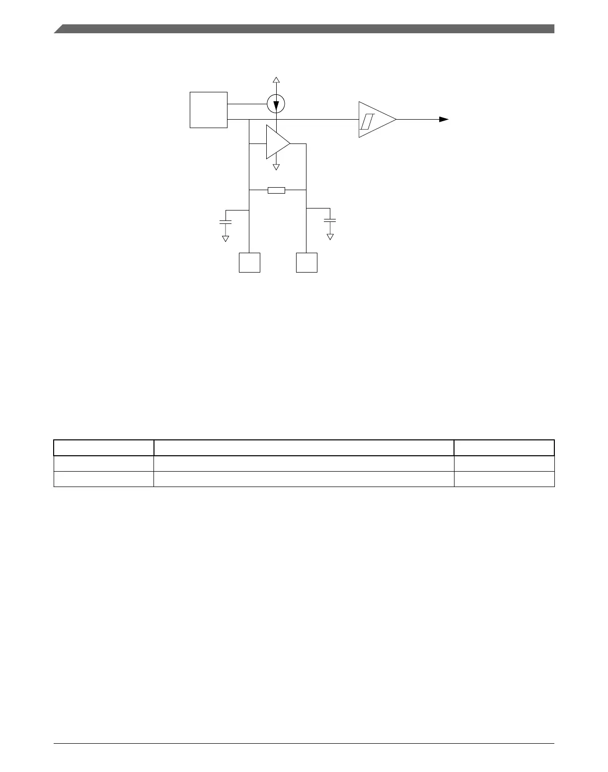
gm
control
clk out for RTC
PAD
PAD
XTAL32
C2
Amplitude
EXTAL32
Rf
C1
detector
Figure 27-1. RTC Oscillator Block Diagram
27.2
RTC Signal Descriptions
The following table shows the user-accessible signals available for the RTC oscillator.
See the chip-level specification to find out which signals are actually connected to the
external pins.
Table 27-1. RTC Signal Descriptions
Signal Description I/O
EXTAL32 Oscillator Input I
XTAL32 Oscillator Output O
27.2.1 EXTAL32 — Oscillator Input
This signal is the analog input of the RTC oscillator.
27.2.2
XTAL32 — Oscillator Output
This signal is the analog output of the RTC oscillator module.
RTC Signal Descriptions
K22F Sub-Family Reference Manual, Rev. 4, 08/2016
590 NXP Semiconductors

 Loading...