46.4.6 Interrupts
The I2C module generates an interrupt when any of the events in the table found here
occur, provided that the IICIE bit is set.
The interrupt is driven by the IICIF bit (of the I2C Status Register) and masked with the
IICIE bit (of the I2C Control Register 1). The IICIF bit must be cleared (by software) by
writing 1 to it in the interrupt routine. The SMBus timeouts interrupt is driven by SLTF
and masked with the IICIE bit. The SLTF bit must be cleared by software by writing 1 to
it in the interrupt routine. You can determine the interrupt type by reading the Status
Register.
NOTE
In master receive mode, the FACK bit must be set to zero
before the last byte transfer.
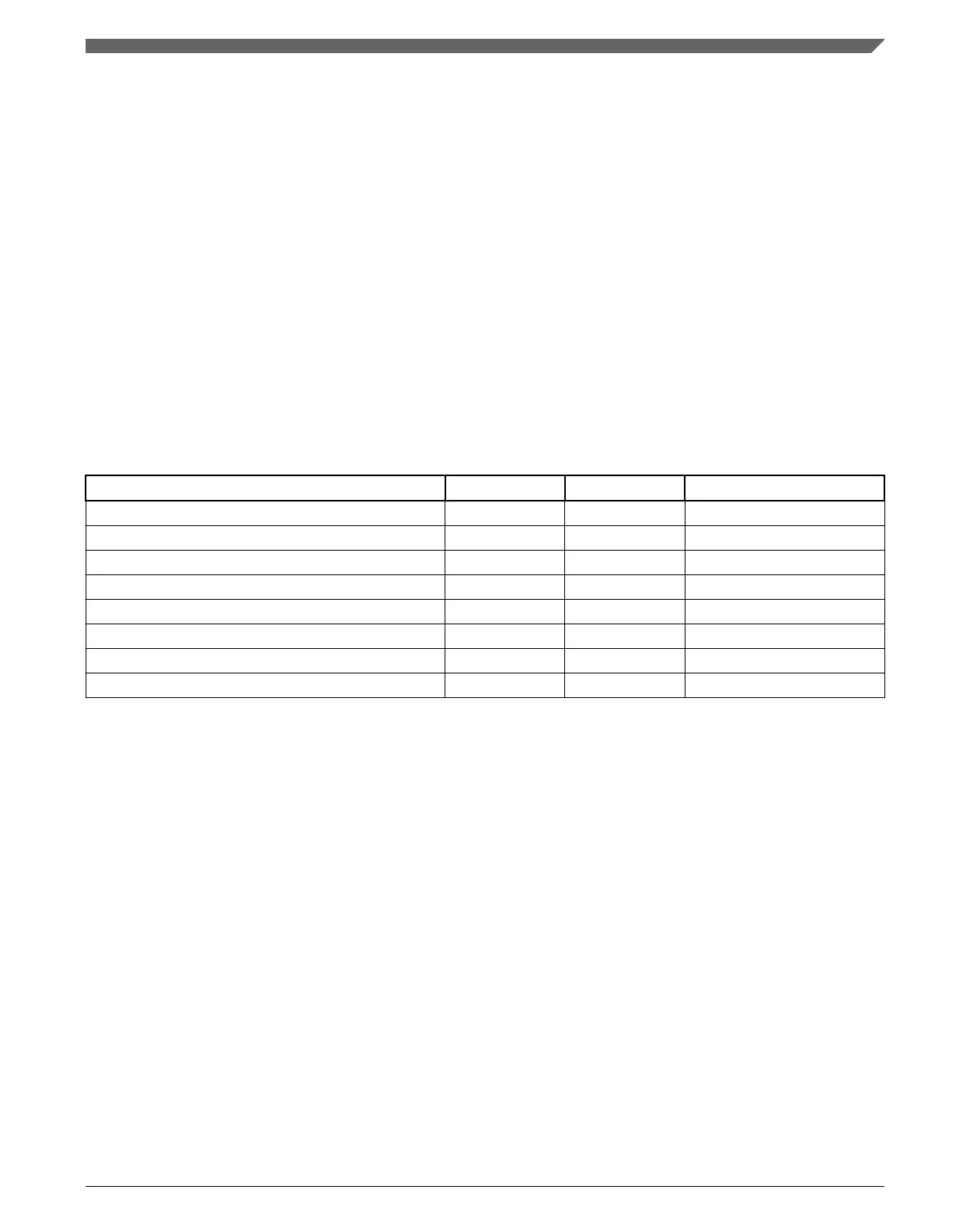
Table 46-5. Interrupt summary
Interrupt source Status Flag Local enable
Complete 1-byte transfer TCF IICIF IICIE
Match of received calling address IAAS IICIF IICIE
Arbitration lost ARBL IICIF IICIE
I
2
C bus stop detection STOPF IICIF IICIE & SSIE
I
2
C bus start detection STARTF IICIF IICIE & SSIE
SMBus SCL low timeout SLTF IICIF IICIE
SMBus SCL high SDA low timeout SHTF2 IICIF IICIE & SHTF2IE
Wakeup from stop or wait mode IAAS IICIF IICIE & WUEN
46.4.6.1 Byte transfer interrupt
The Transfer Complete Flag (TCF) bit is set at the falling edge of the ninth clock to
indicate the completion of a byte and acknowledgement transfer. When FACK is enabled,
TCF is then set at the falling edge of eighth clock to indicate the completion of byte.
46.4.6.2
Address detect interrupt
When the calling address matches the programmed slave address (I2C Address Register)
or when the GCAEN bit is set and a general call is received, the IAAS bit in the Status
Register is set. The CPU is interrupted, provided the IICIE bit is set. The CPU must
check the SRW bit and set its Tx mode accordingly.
Chapter 46 Inter-Integrated Circuit (I2C)
K22F Sub-Family Reference Manual, Rev. 4, 08/2016
NXP Semiconductors 1207

 Loading...