64
MAP
BGA
64
LQFP
80
WLC
SP
88
QFN
100
LQFP
121
MAP
BGA
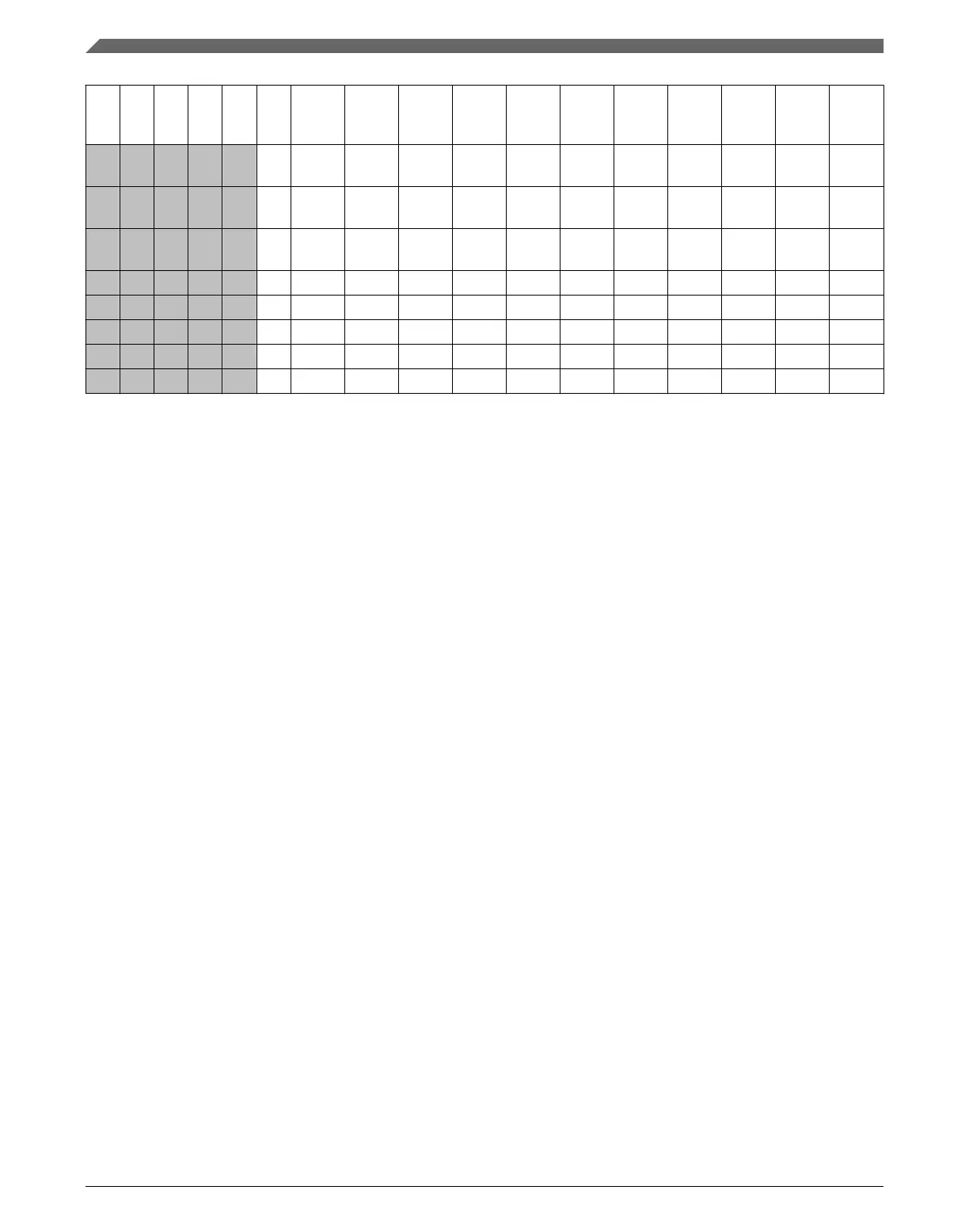
Pin Name Default ALT0 ALT1 ALT2 ALT3 ALT4 ALT5 ALT6 ALT7 EZPORT
— — — — — D2 PTD13 DISABLE
D
PTD13 FB_A21
— — — — — D1 PTD14 DISABLE
D
PTD14 FB_A22
— — — — — E1 PTD15 DISABLE
D
PTD15 FB_A23
— — — — — A11 NC NC NC
— — — — — K3 NC NC NC
— — — — — H4 NC NC NC
— — — — — B11 NC NC NC
— — — — — C11 NC NC NC
10.3.2 K22 Pinouts
The following figure shows the pinout diagram for the devices supported by this
document. Many signals may be multiplexed onto a single pin. To determine what signals
can be used on which pin, see the previous section.
Pinout
K22F Sub-Family Reference Manual, Rev. 4, 08/2016
222 NXP Semiconductors

 Loading...