The delay between the first signal from LPTMR and the second signal from LPTMR
must be greater than the Analog comparator initialization delay as defined in the device
datasheet.
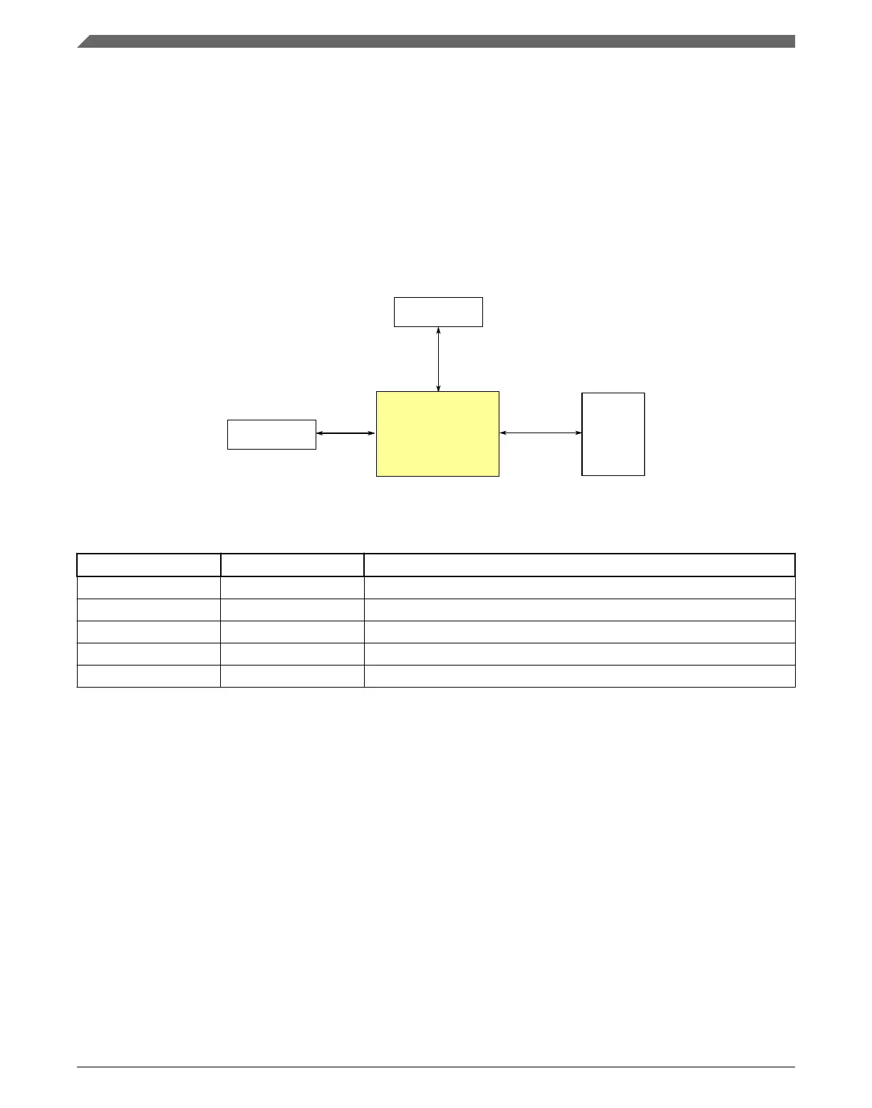
3.7.3 12-bit DAC Configuration
This section summarizes how the module has been configured in the chip. For a
comprehensive description of the module itself, see the module’s dedicated chapter.
Signal
multiplexing
Module signals
Register
access
12-bit DAC
Peripheral bus
controller 0
Other peripherals
Transfers
Figure 3-34. 12-bit DAC configuration
Table 3-48. Reference links to related information
Topic Related module Reference
Full description 12-bit DAC 12-bit DAC
System memory map System memory map
Clocking Clock distribution
Power management Power management
Signal multiplexing Port control Signal multiplexing
3.7.3.1 12-bit DAC Overview
This device contains two 12-bit digital-to-analog converters (DAC) with programmable
reference generator output. The DAC includes a FIFO for DMA support.
3.7.3.2
12-bit DAC Output
The output of the DAC can be placed on an external pin or set as one of the inputs to the
analog comparator or ADC.
Analog
K22F Sub-Family Reference Manual, Rev. 4, 08/2016
106 NXP Semiconductors

 Loading...