Signal Description I/O
LPUART_RX Receive data. I
LPUART_CTS Clear to send. I
LPUART_RTS Request to send. O
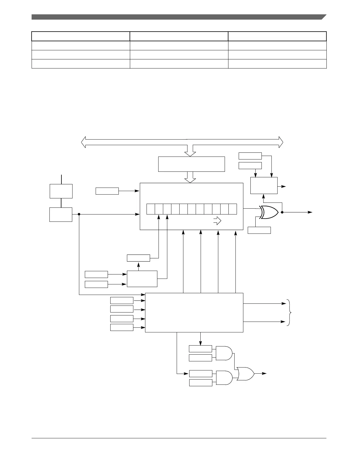
48.1.4 Block diagram
The following figure shows the transmitter portion of the LPUART.
H 8 7 6 5 4 3 2 1 0 L
LPUART_D – Tx Buffer
(Write-Only)
Internal Bus
Stop
11-BIT Transmit Shift Register
Start
SHIFT DIRECTION
lsb
Parity
Generation
Transmit Control
Shift Enable
Preamble (All 1s)
Break (All 0s)
LPUART Controls TxD
TxD Direction
TO TxD
Pin Logic
Loop
Control
To Receive
Data In
To TxD Pin
Tx Interrupt
Request
LOOPS
RSRC
TIE
TC
TDRE
M
PT
PE
TCIE
TE
SBK
T8
TXDIR
Load From LPUARTx_D
TXINV
BRK13
ASYNCH
MODULE
CLOCK
BAUD
Divider
OSR
Divider
Figure 48-1. LPUART transmitter block diagram
The following figure shows the receiver portion of the LPUART.
Chapter 48 Low Power Universal Asynchronous Receiver/Transmitter (LPUART)
K22F Sub-Family Reference Manual, Rev. 4, 08/2016
NXP Semiconductors 1305
 Loading...

