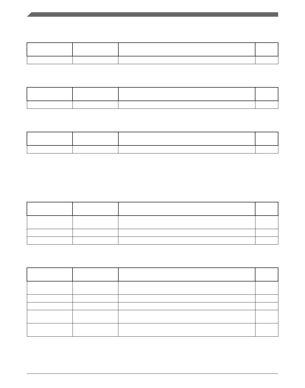
Table 10-15. DAC 0 Signal Descriptions
Chip signal name Module signal
name
Description I/O
DAC0_OUT — DAC output O
Table 10-16. DAC 1 Signal Descriptions
Chip signal name Module signal
name
Description I/O
DAC1_OUT — DAC output O
Table 10-17. VREF Signal Descriptions
Chip signal name Module signal
name
Description I/O
VREF_OUT VREF_OUT Internally-generated Voltage Reference output O
10.4.6 Timer Modules
Table 10-18. FTM 0 Signal Descriptions
Chip signal name Module signal
name
Description I/O
FTM_CLKIN[1:0] EXTCLK External clock. FTM external clock can be selected to drive the
FTM counter.
I
FTM0_CH[7:0] CHn FTM channel (n), where n can be 7-0 I/O
FTM0_FLT[3:0] FAULTj Fault input (j), where j can be 3-0 I
Table 10-19. FTM 1 Signal Descriptions
Chip signal name Module signal
name
Description I/O
FTM_CLKIN[1:0] EXTCLK External clock. FTM external clock can be selected to drive the
FTM counter.
I
FTM1_CH[1:0] CHn FTM channel (n), where n can be 7-0 I/O
FTM1_FLT0 FAULTj Fault input (j), where j can be 3-0 I
FTM1_QD_PHA PHA Quadrature decoder phase A input. Input pin associated with
quadrature decoder phase A.
I
FTM1_QD_PHB PHB Quadrature decoder phase B input. Input pin associated with
quadrature decoder phase B.
I
Module Signal Description Tables
K22F Sub-Family Reference Manual, Rev. 4, 08/2016
234 NXP Semiconductors

 Loading...