1
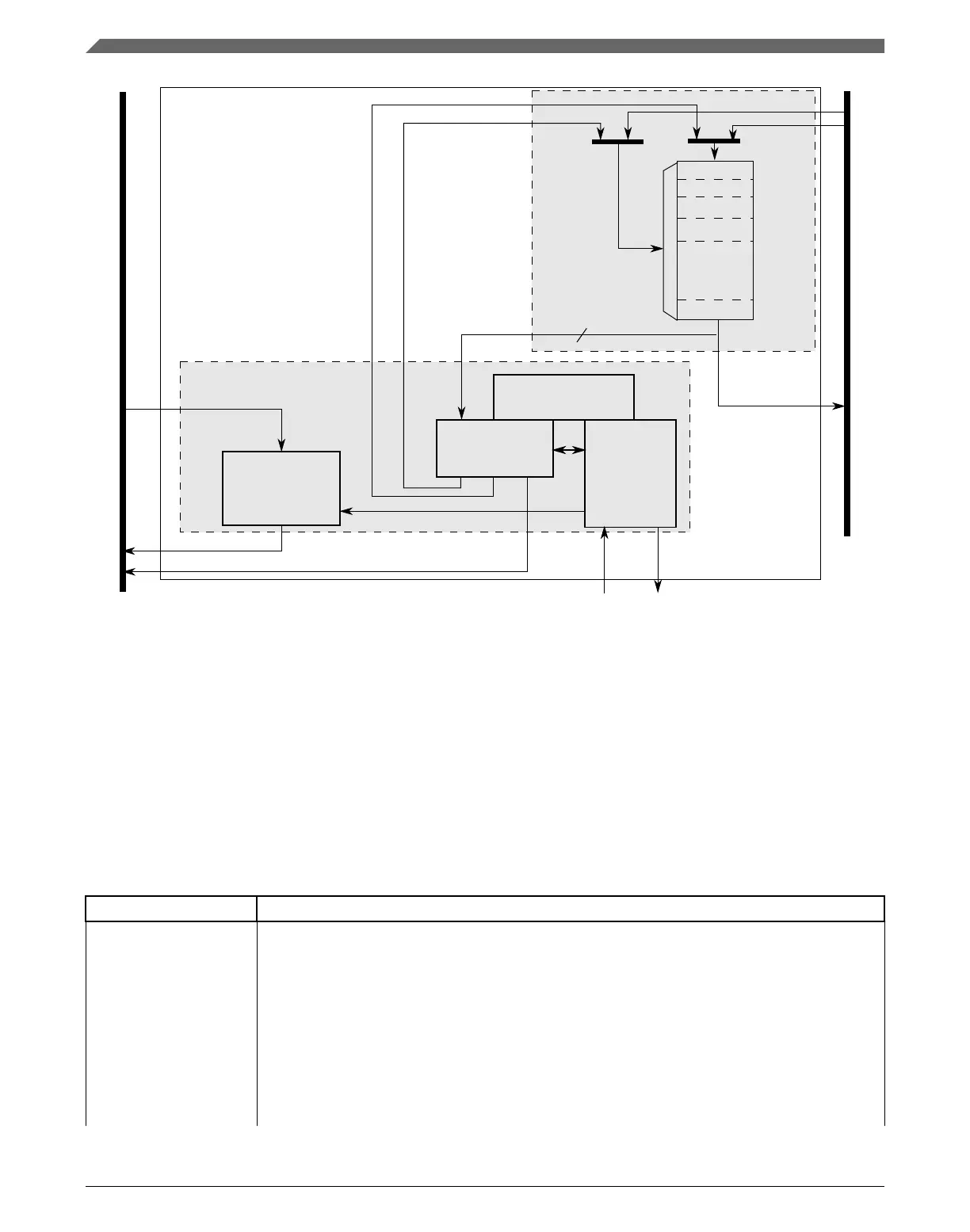
Transfer Control
Descriptor (TCD)
eDMA engine
Data Path
eDMA system
0
Program Model/
64
Control
n-1
To/From Crossbar Switch
2
Channel Arbitration
Address Path
Read Data
Write Data
Address
Read Data
Write Data
Write Address
Internal Peripheral Bus
eDMA Peripheral
Request
eDMA Done
Figure 22-1. eDMA system block diagram
22.1.2
Block parts
The eDMA module is partitioned into two major modules: the eDMA engine and the
transfer-control descriptor local memory.
The eDMA engine is further partitioned into four submodules:
Table 22-1. eDMA engine submodules
Submodule Function
Address path This block implements registered versions of two channel transfer control descriptors, channel x
and channel y, and manages all master bus-address calculations. All the channels provide the
same functionality. This structure allows data transfers associated with one channel to be
preempted after the completion of a read/write sequence if a higher priority channel activation is
asserted while the first channel is active. After a channel is activated, it runs until the minor loop is
completed, unless preempted by a higher priority channel. This provides a mechanism (enabled
by DCHPRIn[ECP]) where a large data move operation can be preempted to minimize the time
another channel is blocked from execution.
When any channel is selected to execute, the contents of its TCD are read from local memory and
loaded into the address path channel x registers for a normal start and into channel y registers for
a preemption start. After the minor loop completes execution, the address path hardware writes
Table continues on the next page...
Introduction
K22F Sub-Family Reference Manual, Rev. 4, 08/2016
426 NXP Semiconductors

 Loading...