Note that the ELSnB:ELSnA bits value should be considered because they define the
active state of the channels outputs. In Low-True (ELSnB:ELSnA = X:1) Combine mode,
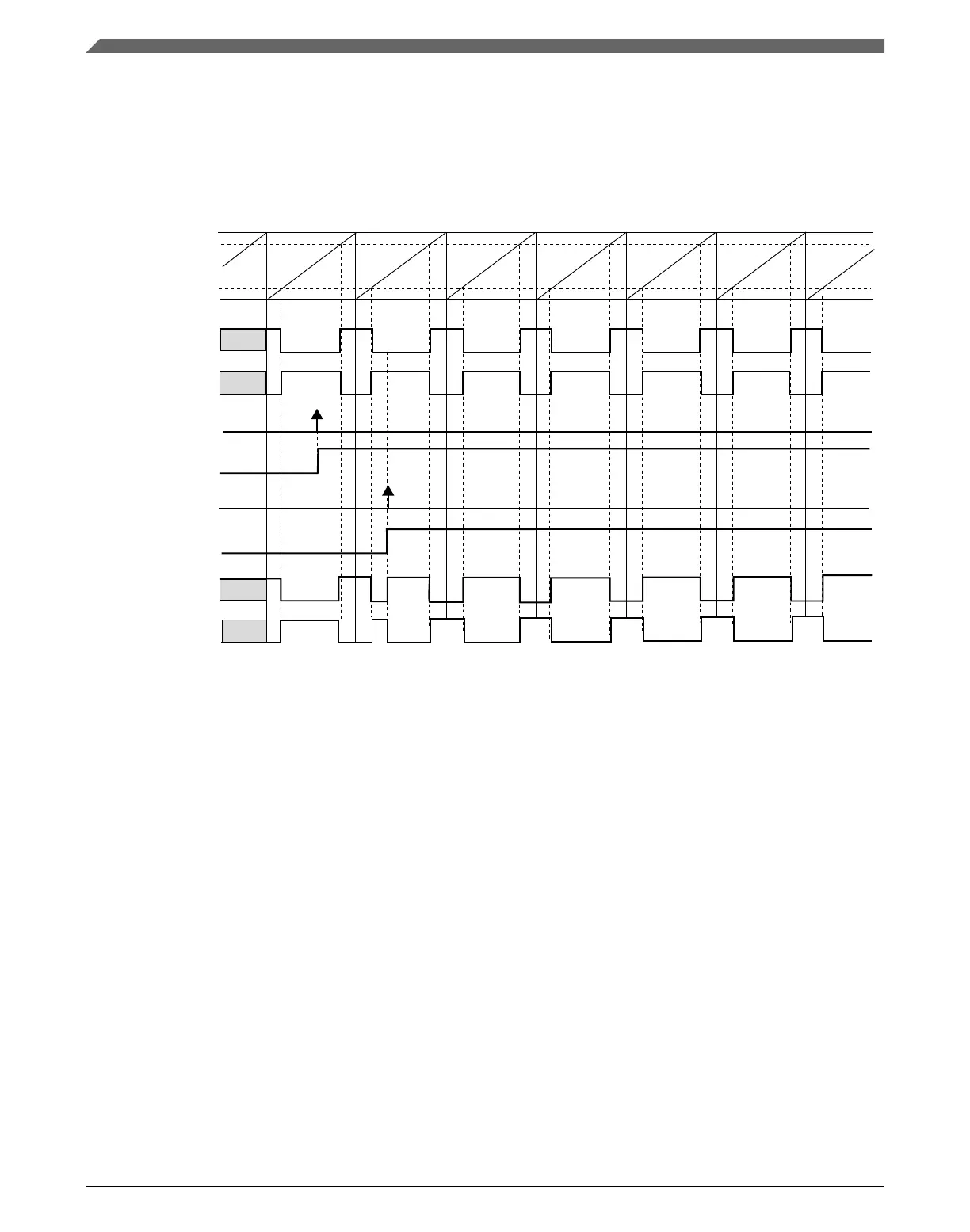
the channel (n) output is forced high at the beginning of the period, forced low at the
channel (n) match and forced high at the channel (n+1) match. When inverting is
selected, the channels (n) and (n+1) present waveforms as shown in the following figure.
NOTE
channel (n+1) match
FTM counter
channel (n) match
channel (n+1) output
before the inverting
write 1 to INV(m) bit
INV(m) bit buffer
INVCTRL register
synchronization
INV(m) bit
channel (n) output
after the inverting
channel (n+1) output
after the inverting
INV(m) bit selects the inverting to the pair channels (n) and (n+1).
channel (n) output
before the inverting
Figure 39-64. Channels (n) and (n+1) outputs after the inverting in Low-True
(ELSnB:ELSnA = X:1) Combine mode
Note
The inverting feature is not available in Output Compare mode.
39.4.13
Software output control
The software output control forces the channel output according to software defined
values at a specific time in the PWM generation.
The software output control is selected when:
• QUADEN = 0
• DECAPEN = 0, and
• CHnOC = 1
Functional description
K22F Sub-Family Reference Manual, Rev. 4, 08/2016
990 NXP Semiconductors

 Loading...