17.3.7 LLWU Flag 2 register (LLWU_F2)
LLWU_F2 contains the wakeup flags indicating which wakeup source caused the MCU
to exit LLS or VLLS mode. For LLS, this is the source causing the CPU interrupt flow.
For VLLS, this is the source causing the MCU reset flow.
The external wakeup flags are read-only and clearing a flag is accomplished by a write of
a 1 to the corresponding WUFx bit. The wakeup flag (WUFx), if set, will remain set if
the associated WUPEx bit is cleared.
NOTE
This register is reset on Chip Reset not VLLS and by reset
types that trigger Chip Reset not VLLS. It is unaffected by reset
types that do not trigger Chip Reset not VLLS. See the
Introduction details for more information.
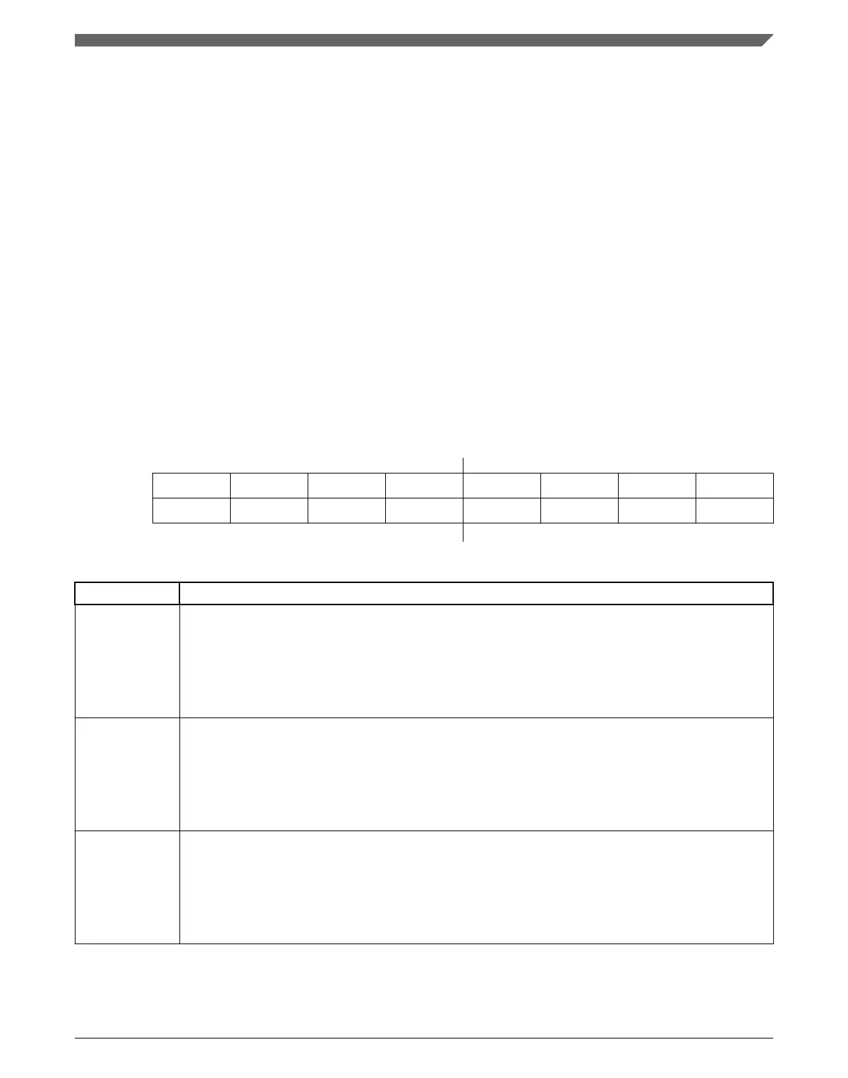
Address:
4007_C000h base + 6h offset = 4007_C006h
Bit 7 6 5 4 3 2 1 0
Read WUF15 WUF14 WUF13 WUF12 WUF11 WUF10 WUF9 WUF8
Write w1c w1c w1c w1c w1c w1c w1c w1c
Reset
0 0 0 0 0 0 0 0
LLWU_F2 field descriptions
Field Description
7
WUF15
Wakeup Flag For LLWU_P15
Indicates that an enabled external wakeup pin was a source of exiting a low-leakage power mode. To
clear the flag, write a 1 to WUF15.
0 LLWU_P15 input was not a wakeup source
1 LLWU_P15 input was a wakeup source
6
WUF14
Wakeup Flag For LLWU_P14
Indicates that an enabled external wakeup pin was a source of exiting a low-leakage power mode. To
clear the flag, write a 1 to WUF14.
0 LLWU_P14 input was not a wakeup source
1 LLWU_P14 input was a wakeup source
5
WUF13
Wakeup Flag For LLWU_P13
Indicates that an enabled external wakeup pin was a source of exiting a low-leakage power mode. To
clear the flag, write a 1 to WUF13.
0 LLWU_P13 input was not a wakeup source
1 LLWU_P13 input was a wakeup source
Table continues on the next page...
Chapter 17 Low-Leakage Wakeup Unit (LLWU)
K22F Sub-Family Reference Manual, Rev. 4, 08/2016
NXP Semiconductors 391

 Loading...