3.7.1.10 ADC low-power modes
This table shows the ADC low-power modes and the corresponding chip low-power
modes.
Table 3-45. ADC low-power modes
Module mode Chip mode
Wait Wait, VLPW
Normal Stop Stop, VLPS
Low Power Stop LLS, VLLS3, VLLS2, VLLS1, VLLS0
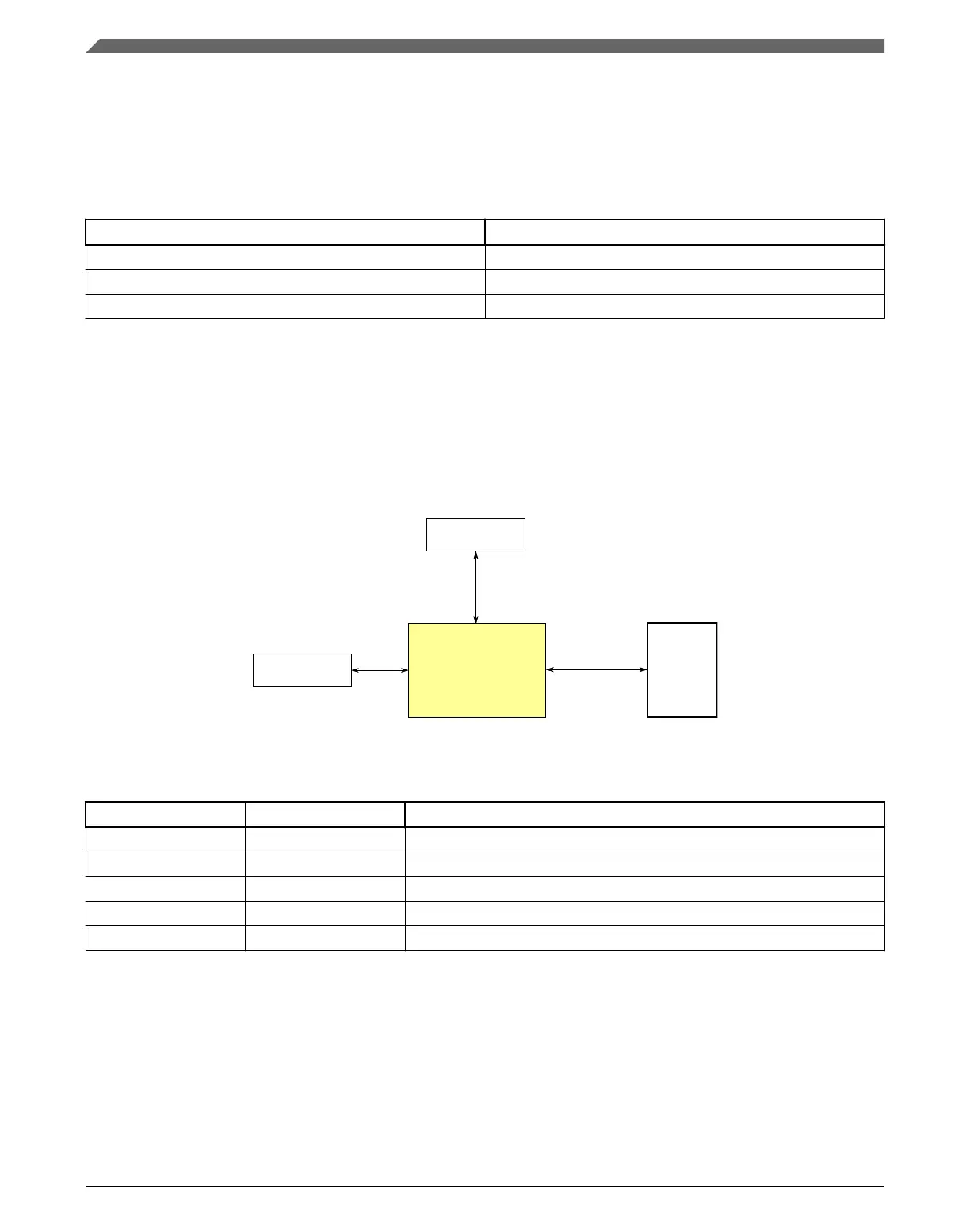
3.7.2 CMP Configuration
This section summarizes how the module has been configured in the chip. For a
comprehensive description of the module itself, see the module’s dedicated chapter.
Signal
multiplexing
Module signals
Register
access
CMP
Peripheral
bridge 0
Other peripherals
Figure 3-33. CMP configuration
Table 3-46. Reference links to related information
Topic Related module Reference
Full description Comparator (CMP) Comparator
System memory map System memory map
Clocking Clock distribution
Power management Power management
Signal multiplexing Port control Signal multiplexing
3.7.2.1 CMP input connections
The following table shows the fixed internal connections to the CMP.
Analog
K22F Sub-Family Reference Manual, Rev. 4, 08/2016
104 NXP Semiconductors

 Loading...