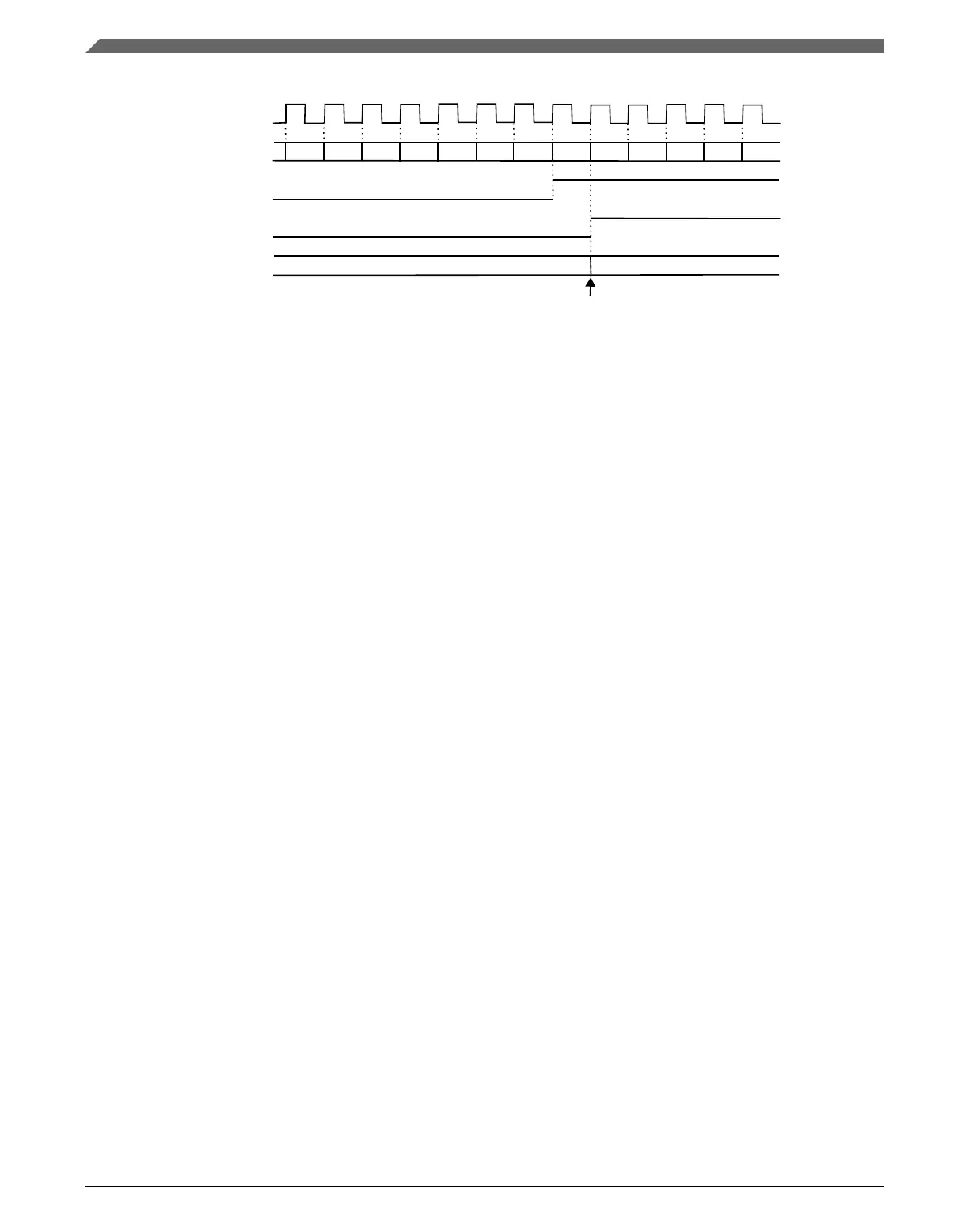
system clock
CNT
channel (n) input
CHnF bit
C(n)V
XX
0x27
selected channel (n) input event: rising edge
NOTE
Channel (n) input after its synchronizer and filter
MOD = 0xFFFF
CNTIN = 0x0000
PS[2:0] = 3'b000
ICRST = 1'b1
...
0x27
...
0x00 0x01 0x02 0x030x260x250x240x230x220x210x20
Figure 39-15. Example of the Input Capture mode with ICRST = 1
NOTE
• It is expected that the ICRST bit be set only when the channel is in input capture
mode.
• In this case, if the FTM counter is reset, then the prescaler counter (Prescaler) and the
TOF counter (When the TOF bit is set) also are reset.
39.4.5
Output Compare mode
The Output Compare mode is selected when:
• DECAPEN = 0
• COMBINE = 0
• CPWMS = 0, and
• MSnB:MSnA = 0:1
In Output Compare mode, the FTM can generate timed pulses with programmable
position, polarity, duration, and frequency. When the counter matches the value in the
CnV register of an output compare channel, the channel (n) output can be set, cleared, or
toggled.
When a channel is initially configured to Toggle mode, the previous value of the channel
output is held until the first output compare event occurs.
The CHnF bit is set and the channel (n) interrupt is generated if CHnIE = 1 at the channel
(n) match (FTM counter = CnV).
Functional description
K22F Sub-Family Reference Manual, Rev. 4, 08/2016
958 NXP Semiconductors

 Loading...