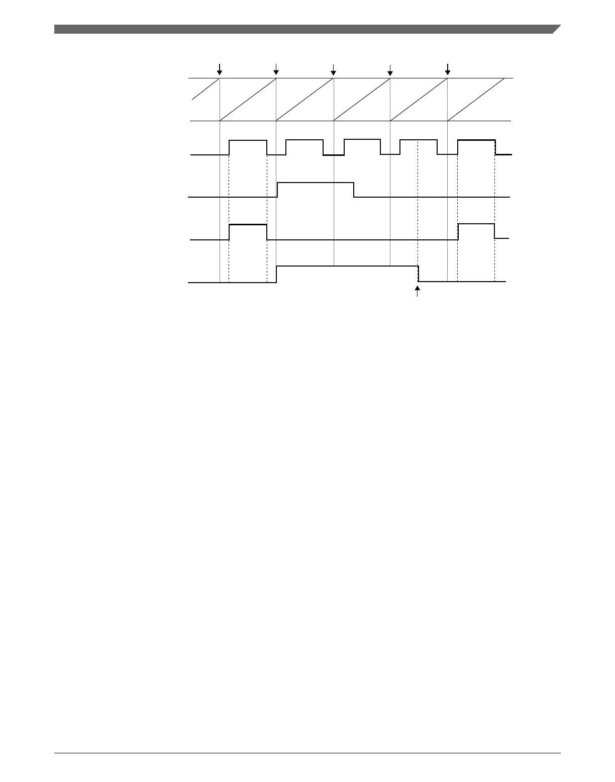
FTM counter
channel (n) output
(before fault control)
FAULTIN bit
channel (n) output
the beginning of new PWM cycles
FAULTF bit
FAULTF bit is cleared
The channel (n) output is after the fault control with manual fault clearing and POLn = 0.
NOTE
Figure 39-74. Fault control with manual fault clearing
39.4.16.3
Fault inputs polarity control
The FLTjPOL bit selects the fault input j polarity, where j = 0, 1, 2, 3:
• If FLTjPOL = 0, the fault j input polarity is high, so the logical one at the fault input j
indicates a fault.
• If FLTjPOL = 1, the fault j input polarity is low, so the logical zero at the fault input j
indicates a fault.
39.4.17
Polarity control
The POLn bit selects the channel (n) output polarity:
• If POLn = 0, the channel (n) output polarity is high, so the logical one is the active
state and the logical zero is the inactive state.
• If POLn = 1, the channel (n) output polarity is low, so the logical zero is the active
state and the logical one is the inactive state.
Chapter 39 FlexTimer Module (FTM)
K22F Sub-Family Reference Manual, Rev. 4, 08/2016
NXP Semiconductors 999

 Loading...