I2Sx_TCR2 field descriptions (continued)
Field Description
Selects the audio Master Clock option used to generate an internally generated bit clock. This field has no
effect when configured for an externally generated bit clock.
NOTE:
Depending on the device, some Master Clock options might not be available. See the chip-
specific information for the meaning of each option.
00 Bus Clock selected.
01 Master Clock (MCLK) 1 option selected.
10 Master Clock (MCLK) 2 option selected.
11 Master Clock (MCLK) 3 option selected.
25
BCP
Bit Clock Polarity
Configures the polarity of the bit clock.
0 Bit clock is active high with drive outputs on rising edge and sample inputs on falling edge.
1 Bit clock is active low with drive outputs on falling edge and sample inputs on rising edge.
24
BCD
Bit Clock Direction
Configures the direction of the bit clock.
0 Bit clock is generated externally in Slave mode.
1 Bit clock is generated internally in Master mode.
23–8
Reserved
This field is reserved.
This read-only field is reserved and always has the value 0.
DIV Bit Clock Divide
Divides down the audio master clock to generate the bit clock when configured for an internal bit clock.
The division value is (DIV + 1) * 2.
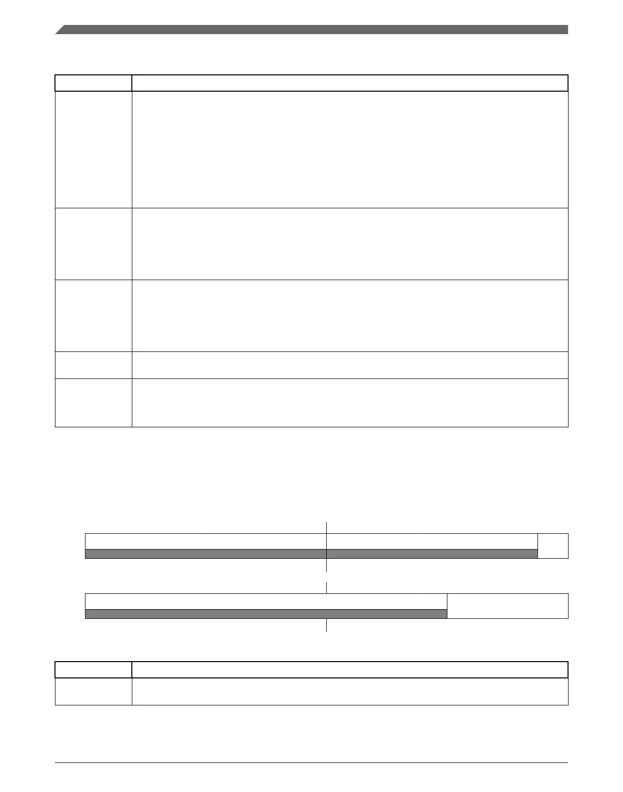
49.3.4 SAI Transmit Configuration 3 Register (I2Sx_TCR3)
Address: 4002_F000h base + Ch offset = 4002_F00Ch
Bit 31 30 29 28 27 26 25 24 23 22 21 20 19 18 17 16
R
0 0
TCE
W
Reset
0 0 0 0 0 0 0 0 0 0 0 0 0 0 0 0
Bit
15 14 13 12 11 10 9 8 7 6 5 4 3 2 1 0
R
0
WDFL
W
Reset
0 0 0 0 0 0 0 0 0 0 0 0 0 0 0 0
I2Sx_TCR3 field descriptions
Field Description
31–24
Reserved
This field is reserved.
This read-only field is reserved and always has the value 0.
Table continues on the next page...
Memory map and register definition
K22F Sub-Family Reference Manual, Rev. 4, 08/2016
1346 NXP Semiconductors

 Loading...