10.4.3 Clock Modules
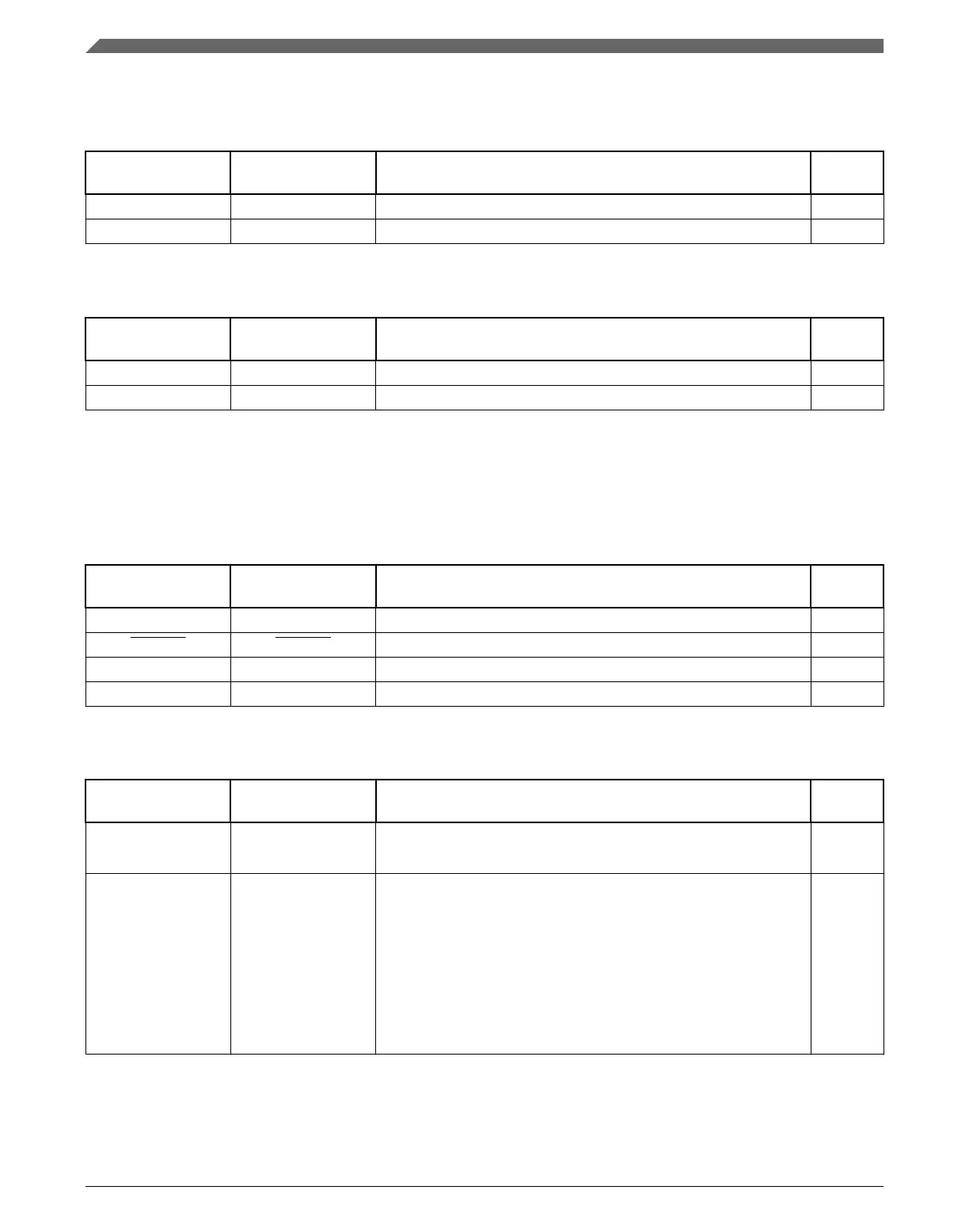
Table 10-7. OSC Signal Descriptions
Chip signal name Module signal
name
Description I/O
EXTAL0 EXTAL External clock/Oscillator input I
XTAL0 XTAL Oscillator output O
Table 10-8. RTC OSC Signal Descriptions
Chip signal name Module signal
name
Description I/O
EXTAL32 EXTAL32 32.768 kHz oscillator input I
XTAL32 XTAL32 32.768 kHz oscillator output O
10.4.4 Memories and Memory Interfaces
Table 10-9. EzPort Signal Descriptions
Chip signal name Module signal
name
Description I/O
EZP_CLK EZP_CK EzPort Clock Input
EZP_CS EZP_CS EzPort Chip Select Input
EZP_DI EZP_D EzPort Serial Data In Input
EZP_DO EZP_Q EzPort Serial Data Out Output
Table 10-10. FlexBus Signal Descriptions
Chip signal name Module signal
name
Description I/O
CLKOUT FB_CLK FlexBus Clock Output O
FB_AD[31:0]
1
FB_AD31 - FB_AD0 This is the address and data bus, FB_AD.
The number of byte lanes carrying the data is determined by the
port size associated with the matching chip-select.
The full 32-bit address is driven on the first clock of a bus cycle
(address phase). After the first clock, the data is driven on the bus
(data phase). During the data phase, the address is driven on the
pins not used for data. For example, in 16-bit mode, the lower
address is driven on FB_AD15–FB_AD0, and in 8-bit mode, the
lower address is driven on FB_AD23–FB_AD0.
I/O
Table continues on the next page...
Module Signal Description Tables
K22F Sub-Family Reference Manual, Rev. 4, 08/2016
230 NXP Semiconductors

 Loading...