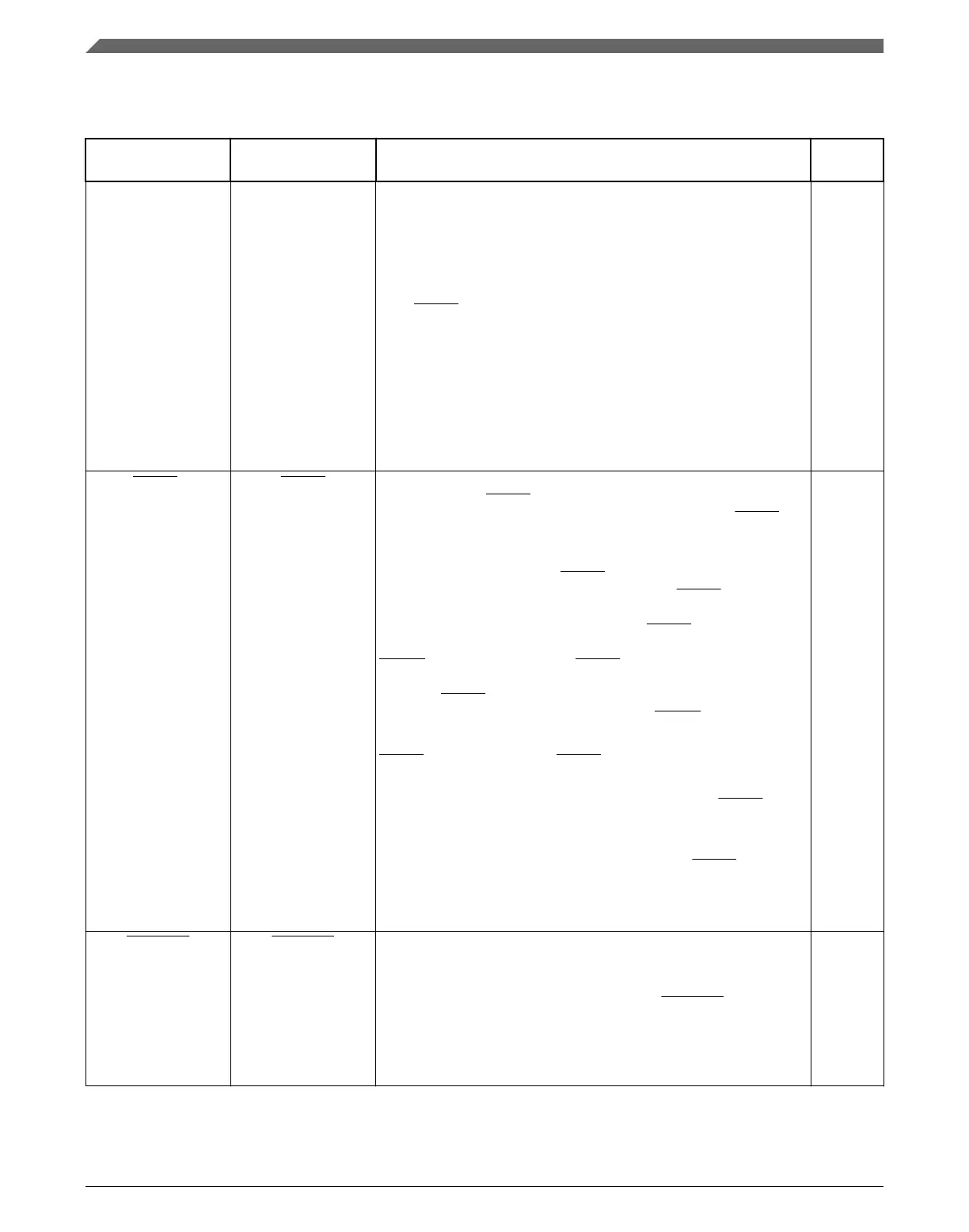
Table 10-10. FlexBus Signal Descriptions
(continued)
Chip signal name Module signal
name
Description I/O
• If bursting is used, FB_TSIZ1–FB_TSIZ0 are driven to the
transfer size.
• If bursting is inhibited, FB_TSIZ1–FB_TSIZ0 first show the
entire transfer size and then show the port size.
For burst-inhibited transfers, FB_TSIZ1–FB_TSIZ0 change with
each FB_TS assertion to reflect the next transfer size.
For transfers to port sizes smaller than the transfer size,
FB_TSIZ1–FB_TSIZ0 indicate the size of the entire transfer on the
first access and the size of the current port transfer on subsequent
transfers. For example, for a 32-bit write to an 8-bit port,
FB_TSIZ1–FB_TSIZ0 are 00b for the first transaction and 01b for
the next three transactions. If bursting is used for a 32-bit write to
an 8-bit port, FB_TSIZ1–FB_TSIZ0 are driven to 00b for the entire
transfer.
FB_TA
4
FB_TA Transfer Acknowledge—Indicates that the external data transfer is
complete. When FB_TA is asserted during a read transfer, FlexBus
latches the data and then terminates the transfer. When FB_TA is
asserted during a write transfer, the transfer is terminated.
If auto-acknowledge is disabled (CSCR[AA] = 0), the external
memory or peripheral drives FB_TA to terminate the transfer. If
auto-acknowledge is enabled (CSCR[AA] = 1), FB_TA is generated
internally after a specified number of wait states, or the external
memory or peripheral may assert external FB_TA before the wait-
state countdown to terminate the transfer early. The chip deasserts
FB_CS one cycle after the last FB_TA is asserted. During read
transfers, the external memory or peripheral must continue to drive
data until FB_TA is recognized. For write transfers, the chip
continues driving data one clock cycle after FB_CS is deasserted.
The number of wait states is determined by CSCR or the external
FB_TA input. If the external FB_TA is used, the external memory or
peripheral has complete control of the number of wait states.
Note:
External memory or peripherals should assert FB_TA only
while the FB_CS signal to the external memory or
peripheral is asserted.
The CSPMCR register controls muxing of FB_TA with other
signals. When the CSPMCR register does not allow fb_ta
control, auto-acknowledge must be used (CSCR[AA] =1'b1);
otherwise the bus may hang.
I
FB_TBST FB_TBST Transfer Burst—Indicates that a burst transfer is in progress as
driven by the chip. A burst transfer can be 2 to 16 beats depending
on FB_TSIZ1–FB_TSIZ0 and the port size.
Note:
When a burst transfer is in progress (FB_TBST = 0b), the
transfer size is 16 bytes (FB_TSIZ1–FB_TSIZ0 = 11b), and
the address is misaligned within the 16-byte boundary, the
external memory or peripheral must be able to wrap around
the address.
O
1. FB_AD[23:21] not available on 100-LQFP devices.
Module Signal Description Tables
K22F Sub-Family Reference Manual, Rev. 4, 08/2016
232 NXP Semiconductors

 Loading...