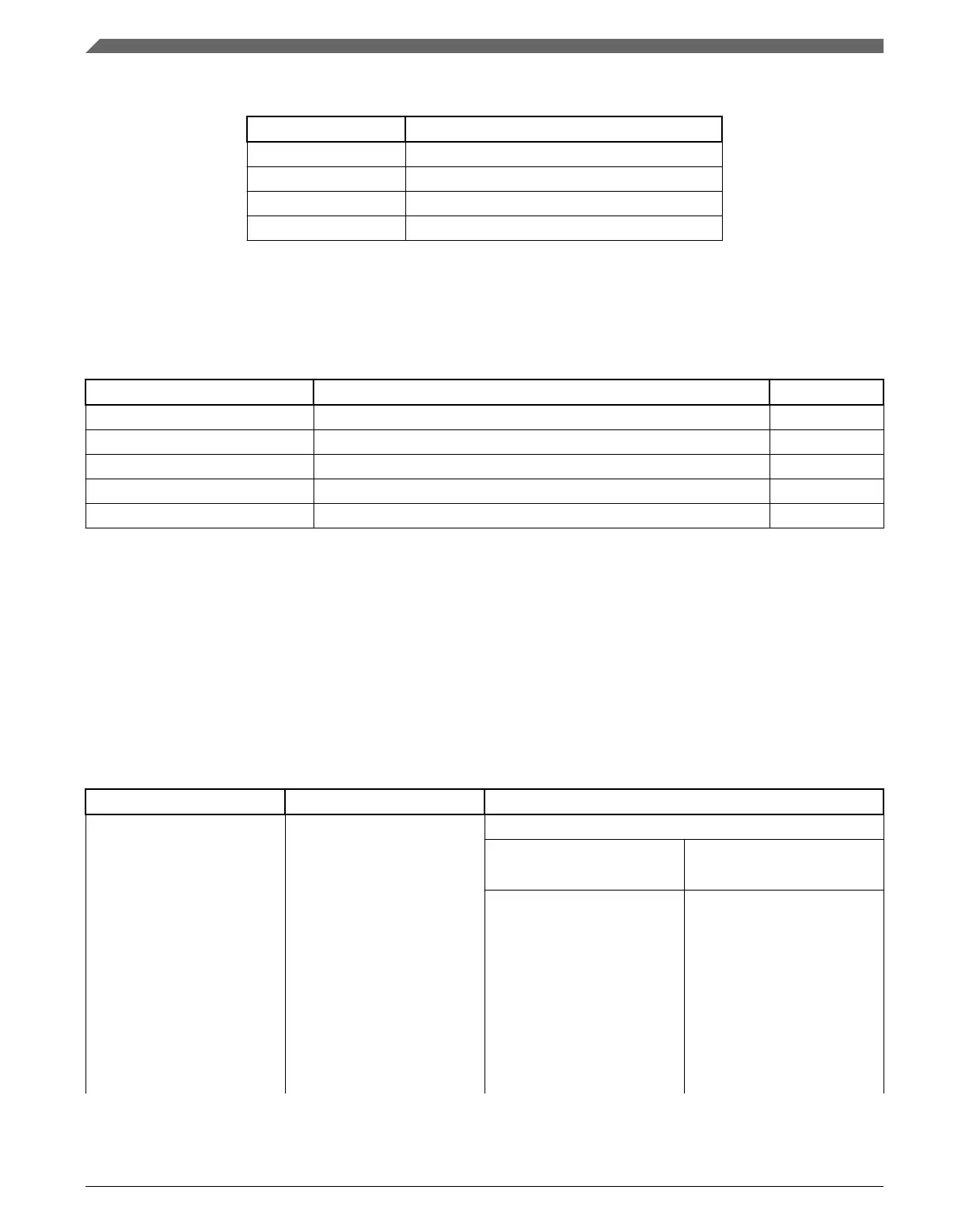
Table 50-1. Modes of operation
Modes of operation Description
Run The GPIO module operates normally.
Wait The GPIO module operates normally.
Stop The GPIO module is disabled.
Debug The GPIO module operates normally.
50.1.3 GPIO signal descriptions
Table 50-2. GPIO signal descriptions
GPIO signal descriptions Description I/O
PORTA31–PORTA0 General-purpose input/output I/O
PORTB31–PORTB0 General-purpose input/output I/O
PORTC31–PORTC0 General-purpose input/output I/O
PORTD31–PORTD0 General-purpose input/output I/O
PORTE31–PORTE0 General-purpose input/output I/O
NOTE
Not all pins within each port are implemented on each device.
See the chapter on signal multiplexing for the number of GPIO
ports available in the device.
50.1.3.1
Detailed signal description
Table 50-3. GPIO interface-detailed signal descriptions
Signal I/O Description
PORTA31–PORTA0
PORTB31–PORTB0
PORTC31–PORTC0
PORTD31–PORTD0
PORTE31–PORTE0
I/O General-purpose input/output
State meaning Asserted: The pin is logic 1.
Deasserted: The pin is logic 0.
Timing Assertion: When output, this
signal occurs on the rising-
edge of the system clock. For
input, it may occur at any time
and input may be asserted
asynchronously to the system
clock.
Deassertion: When output,
this signal occurs on the
rising-edge of the system
clock. For input, it may occur
Introduction
K22F Sub-Family Reference Manual, Rev. 4, 08/2016
1376 NXP Semiconductors

 Loading...