WAS
Polynomial
MUX
CRC Engine
NOT
Logic
Reverse
Logic
Reverse
Logic
[31:24]
[23:16]
[15:8]
[7:0]
CRC Data
Seed
TOT TOTRFXOR
Combine
Logic
TCRC
[31:24]
[23:16]
[15:8]
[7:0]
16-/32-bit Select
CRC Data Register
CRC Polynomial
Register
[31:24]
[23:16]
[15:8]
[7:0]
CRC Data Register
Checksum
Data
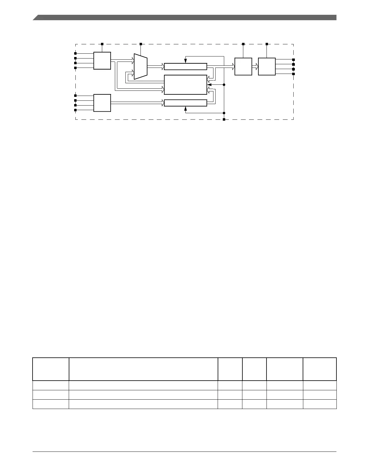
Figure 32-1. Programmable cyclic redundancy check (CRC) block diagram
32.1.3
Modes of operation
Various MCU modes affect the CRC module's functionality.
32.1.3.1 Run mode
This is the basic mode of operation.
32.1.3.2
Low-power modes (Wait or Stop)
Any CRC calculation in progress stops when the MCU enters a low-power mode that
disables the module clock. It resumes after the clock is enabled or via the system reset for
exiting the low-power mode. Clock gating for this module is dependent on the MCU.
32.2
Memory map and register descriptions
CRC memory map
Absolute
address
(hex)
Register name
Width
(in bits)
Access Reset value
Section/
page
4003_2000 CRC Data register (CRC_DATA) 32 R/W FFFF_FFFFh 32.2.1/743
4003_2004 CRC Polynomial register (CRC_GPOLY) 32 R/W 0000_1021h 32.2.2/744
4003_2008 CRC Control register (CRC_CTRL) 32 R/W 0000_0000h 32.2.3/744
Memory map and register descriptions
K22F Sub-Family Reference Manual, Rev. 4, 08/2016
742 NXP Semiconductors

 Loading...