FBE clock mode. The MCG must not be configured in a clock mode where selected IRC
ATM clock is used to generate the system clock. The bus clock is also required to be
running with in the range of 8–16 MHz.
To perform the ATM on the selected IRC, the ATM machine uses the successive
approximation technique to adjust the IRC trim bits to generate the desired IRC trimmed
frequency. The ATM SARs each of the ATM IRC trim bits starting with the MSB. For
each trim bit test, the ATM uses a pulse that is generated by the ATM selected IRC clock
to enable a counter that counts number of ATM external clocks. At end of each trim bit,
the ATM external counter value is compared to the ATCV[15:0] register value. Based on
the comparison result, the ATM trim bit under test will get cleared or stay asserted. This
is done until all trim bits have been tested by ATM SAR machine.
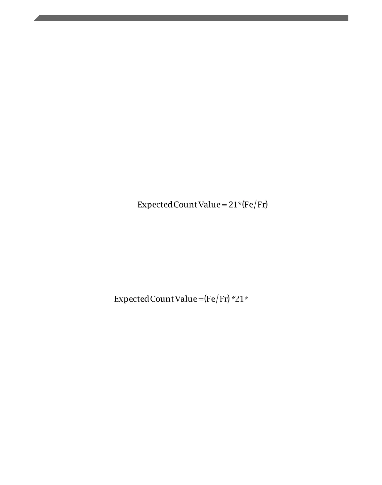
Before the ATM can be enabled, the ATM expected count needs to be derived and stored
into the ATCV register. The ATCV expected count is derived based on the required
target Internal Reference Clock (IRC) frequency, and the frequency of the external
reference clock using the following formula:
• Fr = Target Internal Reference Clock (IRC) Trimmed Frequency
• Fe = External Clock Frequency
If the auto trim is being performed on the 4 MHz IRC, the calculated expected count
value must be multiplied by 128 before storing it in the ATCV register. Therefore, the
ATCV Expected Count Value for trimming the 4 MHz IRC is calculated using the
following formula.
25.5
Initialization / Application information
This section describes how to initialize and configure the MCG module in an application.
The following sections include examples on how to initialize the MCG and properly
switch between the various available modes.
25.5.1
MCG module initialization sequence
The MCG comes out of reset configured for FEI mode.
Initialization / Application information
K22F Sub-Family Reference Manual, Rev. 4, 08/2016
564 NXP Semiconductors

 Loading...