The following table shows how the data direction corresponds to the USB token type in
host and peripheral device applications.
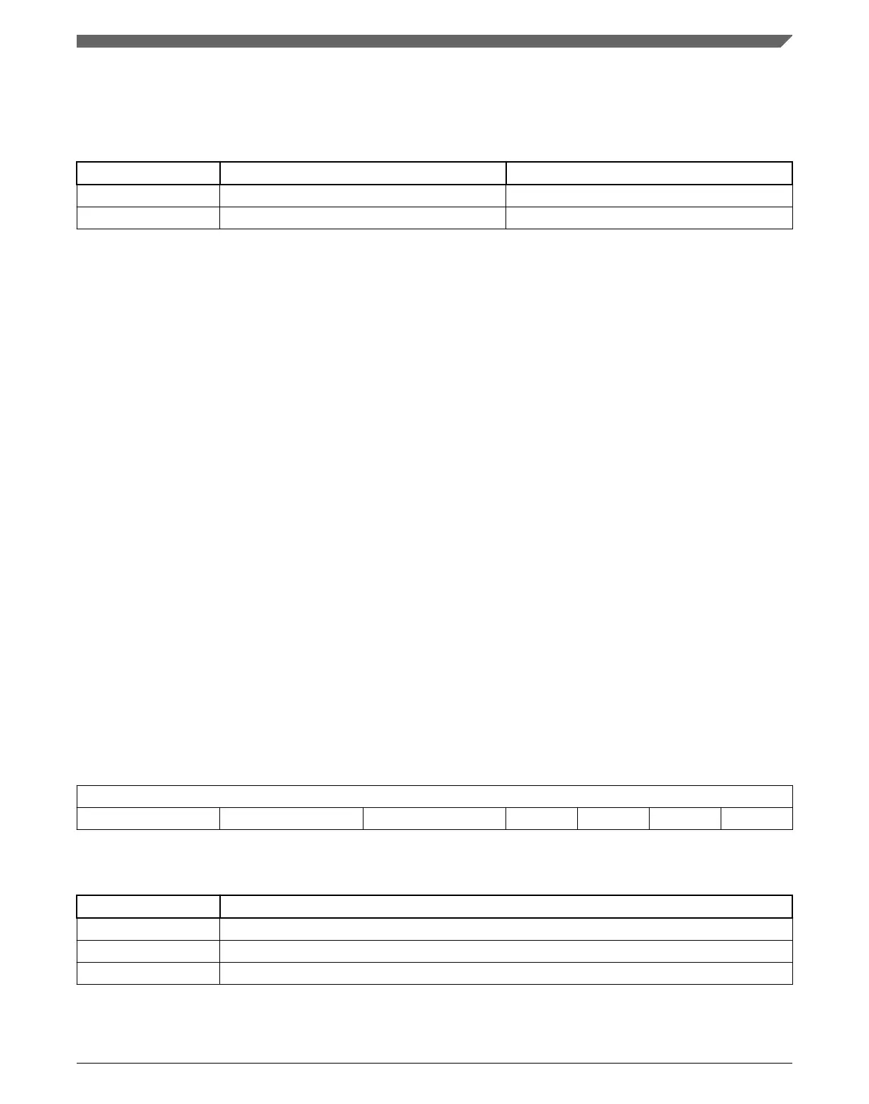
Table 43-1. Data direction for USB host or USB peripheral device
RX TX
Device
OUT or SETUP IN
Host
IN OUT or SETUP
43.3.3 Addressing BDT entries
An understanding of the addressing mechanism of the Buffer Descriptor Table is useful
when accessing endpoint data via USBFS or microprocessor. Some points of interest are:
• The BDT occupies up to 512 bytes of system memory.
• 16 bidirectional endpoints can be supported with a full BDT of 512 bytes.
• 16 bytes are needed for each USB endpoint direction.
• Applications with fewer than 16 endpoints require less RAM to implement the BDT.
• The BDT Page Registers (BDT_PAGE) point to the starting location of the BDT.
• The BDT must be located on a 512-byte boundary in system memory.
• All enabled TX and RX endpoint BD entries are indexed into the BDT to allow easy
access via USBFS or MCU core.
When a USB token on an enabled endpoint is received, USBFS uses its integrated DMA
controller to interrogate the BDT. USBFS reads the corresponding endpoint BD entry to
determine whether it owns the BD and corresponding buffer in system memory.
To compute the entry point into the BDT, the BDT_PAGE registers are concatenated
with the current endpoint and the TX and ODD fields to form a 32-bit address. This
address mechanism is shown in the following tables:
Table 43-2. BDT Address Calculation
31:24 23:16 15:9 8:5 4 3 2:0
BDT_PAGE_03 BDT_PAGE_02 BDT_PAGE_01[7:1] Endpoint TX ODD 000
Table 43-3. BDT address calculation fields
Field Description
BDT_PAGE BDT_PAGE registers in the Control Register Block
ENDPOINT ENDPOINT field from the USB TOKEN
TX 1 for transmit transfers and 0 for receive transfers
Table continues on the next page...
Chapter 43 Universal Serial Bus Full Speed OTG Controller (USBFSOTG)
K22F Sub-Family Reference Manual, Rev. 4, 08/2016
NXP Semiconductors 1077

 Loading...