SMC_PMCTRL field descriptions (continued)
Field Description
001 Reserved
010 Very-Low-Power Stop (VLPS)
011 Low-Leakage Stop (LLSx)
100 Very-Low-Leakage Stop (VLLSx)
101 Reserved
110 Reseved
111 Reserved
15.3.3 Stop Control Register (SMC_STOPCTRL)
The STOPCTRL register provides various control bits allowing the user to fine tune
power consumption during the stop mode selected by the STOPM field.
NOTE
This register is reset on Chip POR not VLLS and by reset types
that trigger Chip POR not VLLS. It is unaffected by reset types
that do not trigger Chip POR not VLLS. See the Reset section
details for more information.
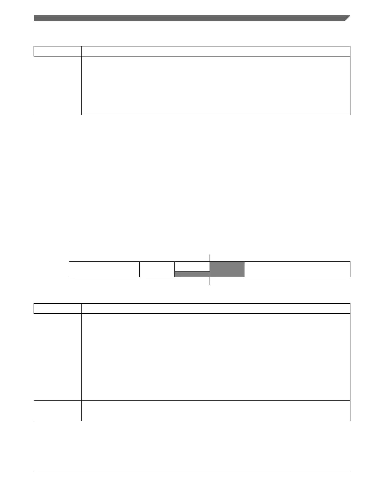
Address:
4007_E000h base + 2h offset = 4007_E002h
Bit 7 6 5 4 3 2 1 0
Read
PSTOPO PORPO
0
Reserved LLSM
Write
Reset
0 0 0 0 0 0 1 1
SMC_STOPCTRL field descriptions
Field Description
7–6
PSTOPO
Partial Stop Option
These bits control whether a Partial Stop mode is entered when STOPM=STOP. When entering a Partial
Stop mode from RUN (or VLPR) mode, the PMC, MCG and flash remain fully powered, allowing the
device to wakeup almost instantaneously at the expense of higher power consumption. In PSTOP2, only
system clocks are gated allowing peripherals running on bus clock to remain fully functional. In PSTOP1,
both system and bus clocks are gated.
00 STOP - Normal Stop mode
01 PSTOP1 - Partial Stop with both system and bus clocks disabled
10 PSTOP2 - Partial Stop with system clock disabled and bus clock enabled
11 Reserved
5
PORPO
POR Power Option
This bit controls whether the POR detect circuit is enabled in VLLS0 mode.
Table continues on the next page...
Chapter 15 System Mode Controller (SMC)
K22F Sub-Family Reference Manual, Rev. 4, 08/2016
NXP Semiconductors 357

 Loading...