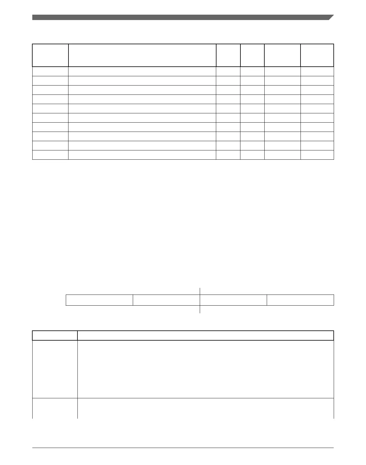
LLWU memory map
Absolute
address
(hex)
Register name
Width
(in bits)
Access Reset value
Section/
page
4007_C000 LLWU Pin Enable 1 register (LLWU_PE1) 8 R/W 00h 17.3.1/383
4007_C001 LLWU Pin Enable 2 register (LLWU_PE2) 8 R/W 00h 17.3.2/384
4007_C002 LLWU Pin Enable 3 register (LLWU_PE3) 8 R/W 00h 17.3.3/385
4007_C003 LLWU Pin Enable 4 register (LLWU_PE4) 8 R/W 00h 17.3.4/386
4007_C004 LLWU Module Enable register (LLWU_ME) 8 R/W 00h 17.3.5/387
4007_C005 LLWU Flag 1 register (LLWU_F1) 8 R/W 00h 17.3.6/389
4007_C006 LLWU Flag 2 register (LLWU_F2) 8 R/W 00h 17.3.7/391
4007_C007 LLWU Flag 3 register (LLWU_F3) 8 R 00h 17.3.8/392
4007_C008 LLWU Pin Filter 1 register (LLWU_FILT1) 8 R/W 00h 17.3.9/394
4007_C009 LLWU Pin Filter 2 register (LLWU_FILT2) 8 R/W 00h 17.3.10/395
17.3.1 LLWU Pin Enable 1 register (LLWU_PE1)
LLWU_PE1 contains the field to enable and select the edge detect type for the external
wakeup input pins LLWU_P3–LLWU_P0.
NOTE
This register is reset on Chip Reset not VLLS and by reset
types that trigger Chip Reset not VLLS. It is unaffected by reset
types that do not trigger Chip Reset not VLLS. See the
Introduction details for more information.
Address:
4007_C000h base + 0h offset = 4007_C000h
Bit 7 6 5 4 3 2 1 0
Read
WUPE3 WUPE2 WUPE1 WUPE0
Write
Reset
0 0 0 0 0 0 0 0
LLWU_PE1 field descriptions
Field Description
7–6
WUPE3
Wakeup Pin Enable For LLWU_P3
Enables and configures the edge detection for the wakeup pin.
00 External input pin disabled as wakeup input
01 External input pin enabled with rising edge detection
10 External input pin enabled with falling edge detection
11 External input pin enabled with any change detection
5–4
WUPE2
Wakeup Pin Enable For LLWU_P2
Enables and configures the edge detection for the wakeup pin.
Table continues on the next page...
Chapter 17 Low-Leakage Wakeup Unit (LLWU)
K22F Sub-Family Reference Manual, Rev. 4, 08/2016
NXP Semiconductors 383

 Loading...