23.2 EWM Signal Descriptions
The EWM has two external signals, as shown in the following table.
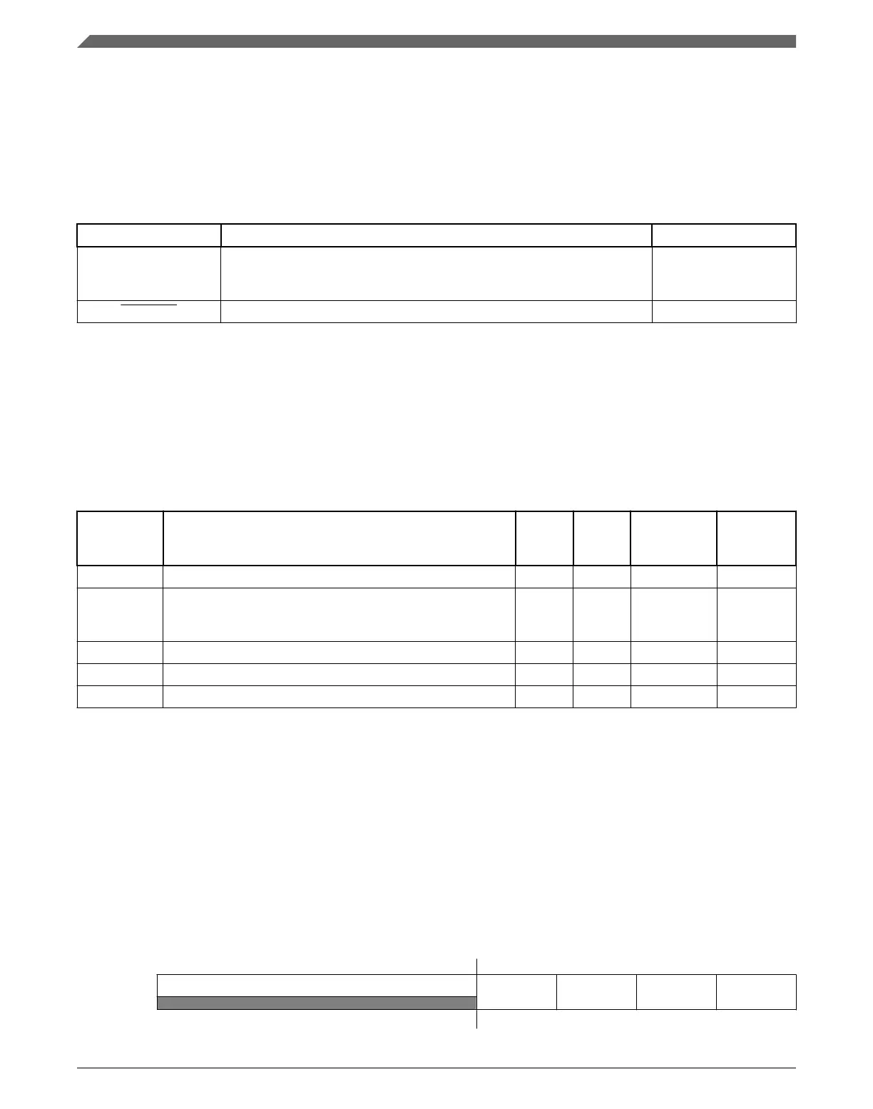
Table 23-1. EWM Signal Descriptions
Signal Description I/O
EWM_in EWM input for safety status of external safety circuits. The polarity of
EWM_in is programmable using the EWM_CTRL[ASSIN] bit. The default
polarity is active-low.
I
EWM_out EWM reset out signal O
23.3 Memory Map/Register Definition
This section contains the module memory map and registers.
EWM memory map
Absolute
address
(hex)
Register name
Width
(in bits)
Access Reset value
Section/
page
4006_1000 Control Register (EWM_CTRL) 8 R/W 00h 23.3.1/512
4006_1001 Service Register (EWM_SERV) 8
W
(always
reads 0)
00h 23.3.2/513
4006_1002 Compare Low Register (EWM_CMPL) 8 R/W 00h 23.3.3/513
4006_1003 Compare High Register (EWM_CMPH) 8 R/W FFh 23.3.4/514
4006_1005 Clock Prescaler Register (EWM_CLKPRESCALER) 8 R/W 00h 23.3.5/515
23.3.1 Control Register (EWM_CTRL)
The CTRL register is cleared by any reset.
NOTE
INEN, ASSIN and EWMEN bits can be written once after a
CPU reset. Modifying these bits more than once, generates a
bus transfer error.
Address:
4006_1000h base + 0h offset = 4006_1000h
Bit 7 6 5 4 3 2 1 0
Read 0
INTEN INEN ASSIN EWMEN
Write
Reset
0 0 0 0 0 0 0 0
EWM Signal Descriptions
K22F Sub-Family Reference Manual, Rev. 4, 08/2016
512 NXP Semiconductors

 Loading...