ADCx_CFG1 field descriptions (continued)
Field Description
0 Short sample time.
1 Long sample time.
3–2
MODE
Conversion mode selection
Selects the ADC resolution mode.
00 When DIFF=0:It is single-ended 8-bit conversion; when DIFF=1, it is differential 9-bit conversion with
2's complement output.
01 When DIFF=0:It is single-ended 12-bit conversion ; when DIFF=1, it is differential 13-bit conversion
with 2's complement output.
10 When DIFF=0:It is single-ended 10-bit conversion. ; when DIFF=1, it is differential 11-bit conversion
with 2's complement output
11 When DIFF=0:It is single-ended 16-bit conversion..; when DIFF=1, it is differential 16-bit conversion
with 2's complement output
ADICLK Input Clock Select
Selects the input clock source to generate the internal clock, ADCK. Note that when the ADACK clock
source is selected, it is not required to be active prior to conversion start. When it is selected and it is not
active prior to a conversion start, when CFG2[ADACKEN]=0, the asynchronous clock is activated at the
start of a conversion and deactivated when conversions are terminated. In this case, there is an
associated clock startup delay each time the clock source is re-activated.
00 Bus clock
01 Alternate clock 2 (ALTCLK2)
10 Alternate clock (ALTCLK)
11 Asynchronous clock (ADACK)
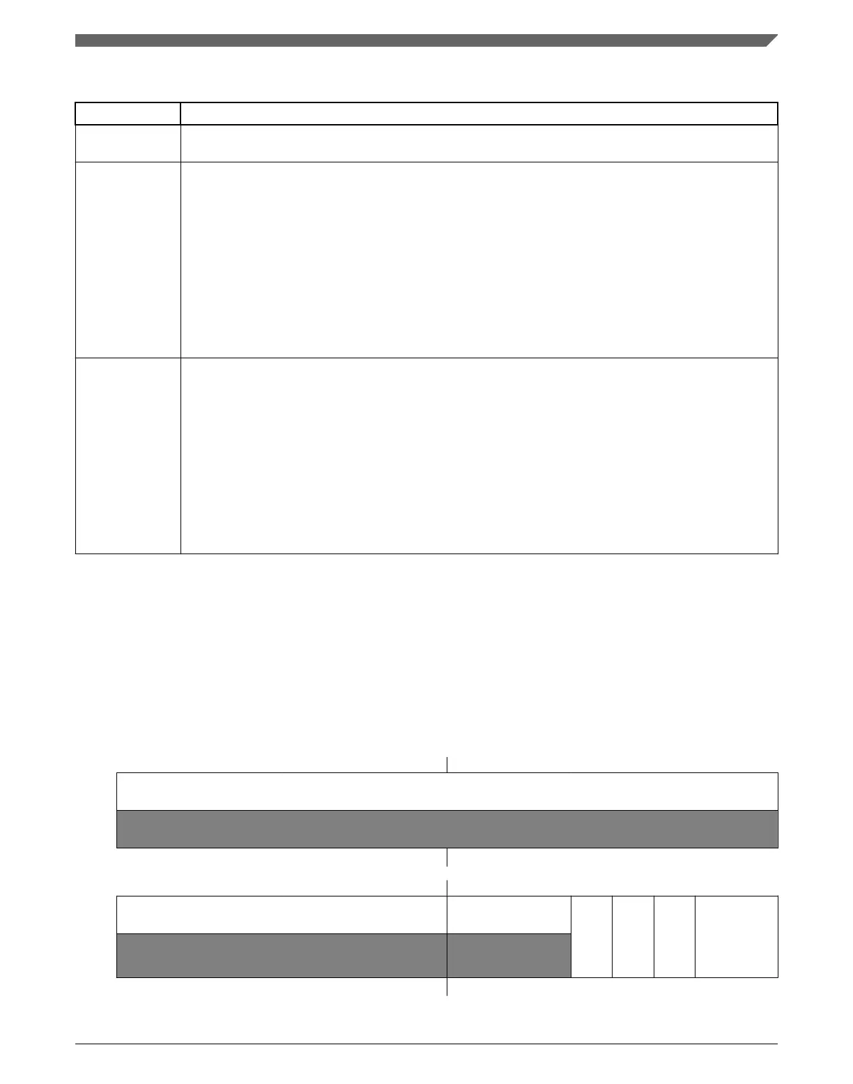
34.3.3 ADC Configuration Register 2 (ADCx_CFG2)
Configuration Register 2 (CFG2) selects the special high-speed configuration for very
high speed conversions and selects the long sample time duration during long sample
mode.
Address:
Base address + Ch offset
Bit 31 30 29 28 27 26 25 24 23 22 21 20 19 18 17 16
R
0
W
Reset
0 0 0 0 0 0 0 0 0 0 0 0 0 0 0 0
Bit
15 14 13 12 11 10 9 8 7 6 5 4 3 2 1 0
R
0 0
MUXSEL
ADACKEN
ADHSC
ADLSTS
W
Reset
0 0 0 0 0 0 0 0 0 0 0 0 0 0 0 0
Chapter 34 Analog-to-Digital Converter (ADC)
K22F Sub-Family Reference Manual, Rev. 4, 08/2016
NXP Semiconductors 773

 Loading...