FTMx_SYNC field descriptions (continued)
Field Description
1
CNTMAX
Maximum Loading Point Enable
Selects the maximum loading point to PWM synchronization. See Boundary cycle and loading points. If
CNTMAX is 1, the selected loading point is when the FTM counter reaches its maximum value (MOD
register).
0 The maximum loading point is disabled.
1 The maximum loading point is enabled.
0
CNTMIN
Minimum Loading Point Enable
Selects the minimum loading point to PWM synchronization. See Boundary cycle and loading points. If
CNTMIN is one, the selected loading point is when the FTM counter reaches its minimum value (CNTIN
register).
0 The minimum loading point is disabled.
1 The minimum loading point is enabled.
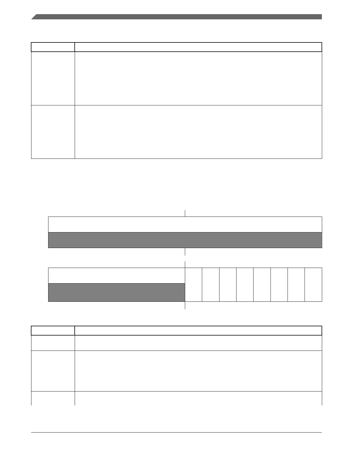
39.3.12 Initial State For Channels Output (FTMx_OUTINIT)
Address: Base address + 5Ch offset
Bit 31 30 29 28 27 26 25 24 23 22 21 20 19 18 17 16
R
0
W
Reset
0 0 0 0 0 0 0 0 0 0 0 0 0 0 0 0
Bit
15 14 13 12 11 10 9 8 7 6 5 4 3 2 1 0
R
0
CH7OI
CH6OI
CH5OI
CH4OI
CH3OI
CH2OI
CH1OI
CH0OI
W
Reset
0 0 0 0 0 0 0 0 0 0 0 0 0 0 0 0
FTMx_OUTINIT field descriptions
Field Description
31–8
Reserved
This field is reserved.
This read-only field is reserved and always has the value 0.
7
CH7OI
Channel 7 Output Initialization Value
Selects the value that is forced into the channel output when the initialization occurs.
0 The initialization value is 0.
1 The initialization value is 1.
6
CH6OI
Channel 6 Output Initialization Value
Table continues on the next page...
Memory map and register definition
K22F Sub-Family Reference Manual, Rev. 4, 08/2016
916 NXP Semiconductors

 Loading...