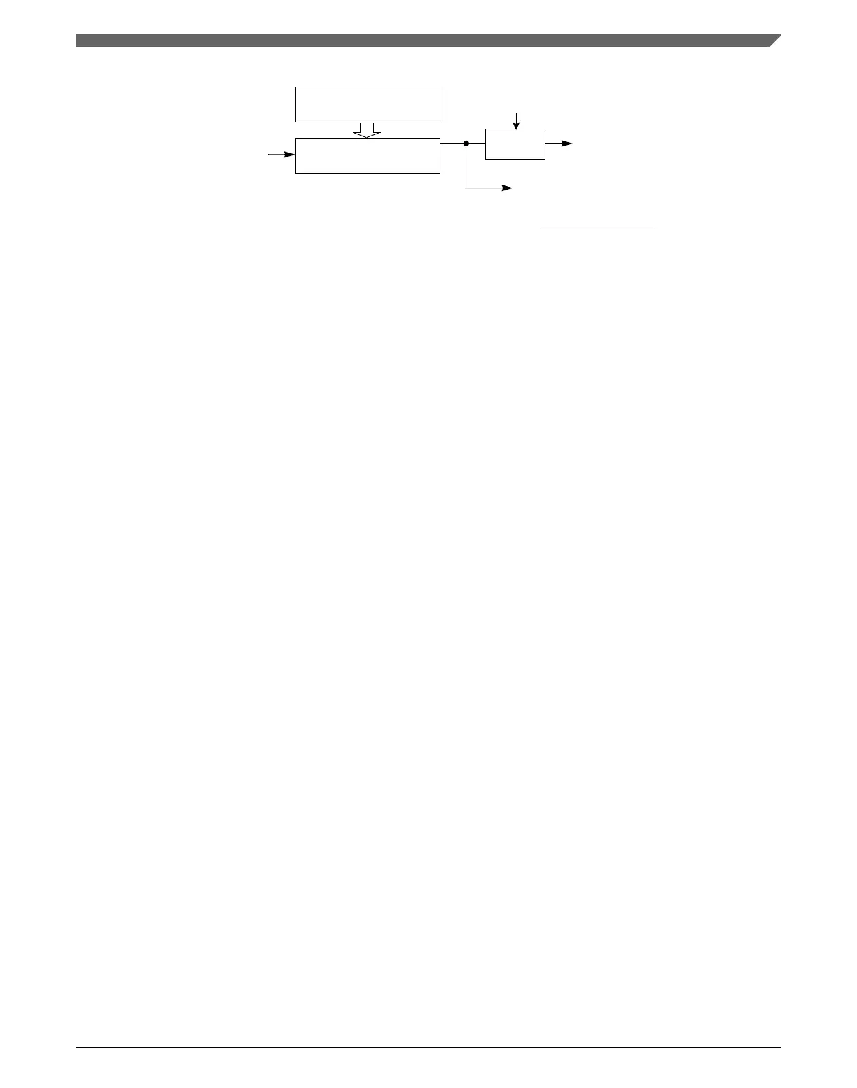
Rx Sampling Clock
[(OSR+1) × Baud Rate]
Baud Rate =
Modulo Divide By
(1 through 8191)
LPUART ASYNCH
Module Clock
LPUART ASYNCH Module Clock
Divide By
(OSR+1)
OSR
SBR[12:0]
Baud Rate Generator
Off If [SBR12:SBR0] =0
SBR[12:0] × (OSR+1)
Tx Baud Rate
Figure 48-3. LPUART baud rate generation
Baud rate generation is subject to two sources of error:
• Integer division of the asynchronous LPUART baud clock may not give the exact
target frequency.
• Synchronization with the asynchronous LPUART baud clock can cause phase shift.
48.3.2
Transmitter functional description
This section describes the overall block diagram for the LPUART transmitter, as well as
specialized functions for sending break and idle characters.
The transmitter output (LPUART_TX) idle state defaults to logic high, CTRL[TXINV] is
cleared following reset. The transmitter output is inverted by setting CTRL[TXINV]. The
transmitter is enabled by setting the CTRL[TE] bit. This queues a preamble character that
is one full character frame of the idle state. The transmitter then remains idle until data is
available in the transmit data buffer. Programs store data into the transmit data buffer by
writing to the LPUART data register.
The central element of the LPUART transmitter is the transmit shift register that is 10-bit
to 13 bits long depending on the setting in the CTRL[M], BAUD[M10] and
BAUD[SBNS] control bits. For the remainder of this section, assume CTRL[M],
BAUD[M10] and BAUD[SBNS] are cleared, selecting the normal 8-bit data mode. In 8-
bit data mode, the shift register holds a start bit, eight data bits, and a stop bit. When the
transmit shift register is available for a new character, the value waiting in the transmit
data register is transferred to the shift register, synchronized with the baud rate clock, and
the transmit data register empty (STAT[TDRE]) status flag is set to indicate another
character may be written to the transmit data buffer at LPUART_DATA.
If no new character is waiting in the transmit data buffer after a stop bit is shifted out the
LPUART_TX pin, the transmitter sets the transmit complete flag and enters an idle
mode, with LPUART_TX high, waiting for more characters to transmit.
Chapter 48 Low Power Universal Asynchronous Receiver/Transmitter (LPUART)
K22F Sub-Family Reference Manual, Rev. 4, 08/2016
NXP Semiconductors 1323

 Loading...