SIM_FCFG1 field descriptions (continued)
Field Description
23–20
Reserved
This field is reserved.
This read-only field is reserved and always has the value 0.
19–16
Reserved
This field is reserved.
This read-only field is reserved and always has the value 1.
15–12
Reserved
This field is reserved.
This read-only field is reserved and always has the value 0.
11–8
Reserved
This field is reserved.
This read-only field is reserved and always has the value 1.
7–2
Reserved
This field is reserved.
This read-only field is reserved and always has the value 0.
1
FLASHDOZE
Flash Doze
When set, Flash memory is disabled for the duration of Wait mode. An attempt by the DMA or other bus
master to access the Flash when the Flash is disabled will result in a bus error. This bit should be clear
during VLP modes. The Flash will be automatically enabled again at the end of Wait mode so interrupt
vectors do not need to be relocated out of Flash memory. The wakeup time from Wait mode is extended
when this bit is set.
0 Flash remains enabled during Wait mode
1 Flash is disabled for the duration of Wait mode
0
FLASHDIS
Flash Disable
Flash accesses are disabled (and generate a bus error) and the Flash memory is placed in a low power
state. This bit should not be changed during VLP modes. Relocate the interrupt vectors out of Flash
memory before disabling the Flash.
0 Flash is enabled
1 Flash is disabled
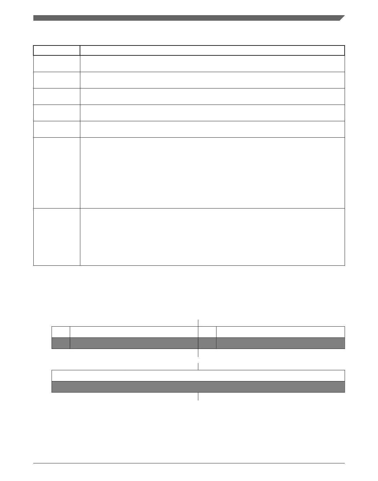
12.2.16 Flash Configuration Register 2 (SIM_FCFG2)
Address: 4004_7000h base + 1050h offset = 4004_8050h
Bit 31 30 29 28 27 26 25 24 23 22 21 20 19 18 17 16
R
0 MAXADDR0 1 MAXADDR1
W
Reset
0* 1* 1* 1* 1* 1* 1* 1* 1* 1* 1* 1* 1* 1* 1* 1*
Bit
15 14 13 12 11 10 9 8 7 6 5 4 3 2 1 0
R
0
W
Reset
0* 0* 0* 0* 0* 0* 0* 0* 0* 0* 0* 0* 0* 0* 0* 0*
Chapter 12 System Integration Module (SIM)
K22F Sub-Family Reference Manual, Rev. 4, 08/2016
NXP Semiconductors 289

 Loading...