gtb_in
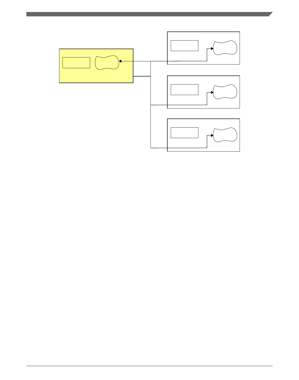
FTM1
GTBEEN = 1
FTM Counter
CONF Register
GTBEOUT = 0
FTM0
GTBEEN = 1
FTM Counter
CONF Register
GTBEOUT = 1
gtb_out
gtb_in
gtb_in
FTM2
GTBEEN = 1
FTM Counter
CONF Register
GTBEOUT = 0
gtb_in
FTM3
GTBEEN = 1
FTM Counter
CONF Register
GTBEOUT = 0
Figure 3-41. FTM Global Time Base Configuration
3.8.2.12
FTM BDM and debug halt mode
In the FTM chapter, references to the chip being in "BDM" are the same as the chip being
in “debug halt mode".
3.8.3
PIT Configuration
This section summarizes how the module has been configured in the chip. For a
comprehensive description of the module itself, see the module’s dedicated chapter.
Chapter 3 Chip Configuration
K22F Sub-Family Reference Manual, Rev. 4, 08/2016
NXP Semiconductors 117

 Loading...