1. Halt it by setting MCR[HALT].
2. Clear the transmit and receive FIFOs by writing a 1 to the CLR_TXF and CLR_RXF
bits in MCR.
3. Set the appropriate mode in MCR[MSTR] and enable it by clearing MCR[HALT].
45.5.3 Initializing Module in Master/Slave Modes
Once the appropriate mode in MCR[MSTR] is configured, the module is enabled by
clearing MCR[HALT]. It should be ensured that module Slave is enabled before enabling
it's Master. This ensures the Slave is ready to be communicated with, before Master
initializes communication.
45.5.4
Baud rate settings
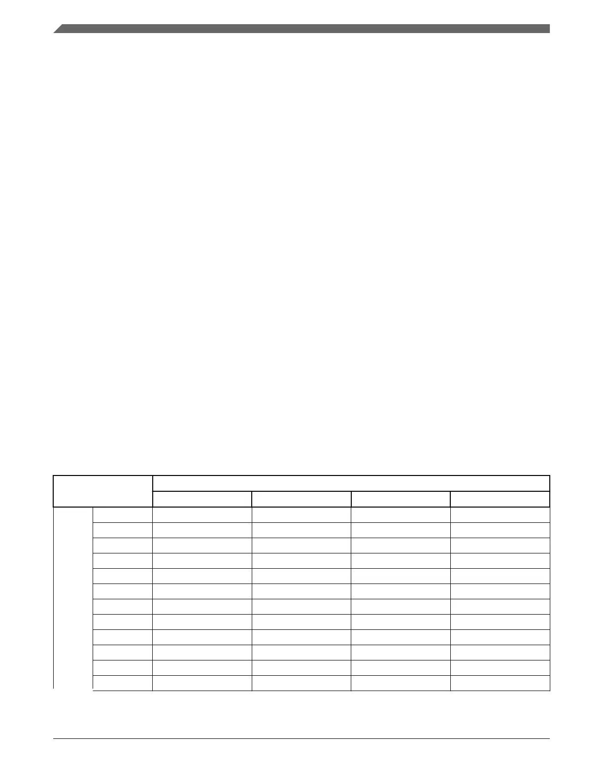
The following table shows the baud rate that is generated based on the combination of the
baud rate prescaler PBR and the baud rate scaler BR in the CTARs. The values calculated
assume a 100 MHz protocol frequency and the double baud rate DBR bit is cleared.
NOTE
The clock frequency mentioned above is given as an example in
this chapter. See the clocking chapter for the frequency used to
drive this module in the device.
Table 45-12. Baud rate values (bps)
Baud rate divider prescaler values
2 3 5 7
Baud Rate Scaler Values
2 25.0M 16.7M 10.0M 7.14M
4 12.5M 8.33M 5.00M 3.57M
6 8.33M 5.56M 3.33M 2.38M
8 6.25M 4.17M 2.50M 1.79M
16 3.12M 2.08M 1.25M 893k
32 1.56M 1.04M 625k 446k
64 781k 521k 312k 223k
128 391k 260k 156k 112k
256 195k 130k 78.1k 55.8k
512 97.7k 65.1k 39.1k 27.9k
1024 48.8k 32.6k 19.5k 14.0k
2048 24.4k 16.3k 9.77k 6.98k
Table continues on the next page...
Initialization/application information
K22F Sub-Family Reference Manual, Rev. 4, 08/2016
1176 NXP Semiconductors

 Loading...