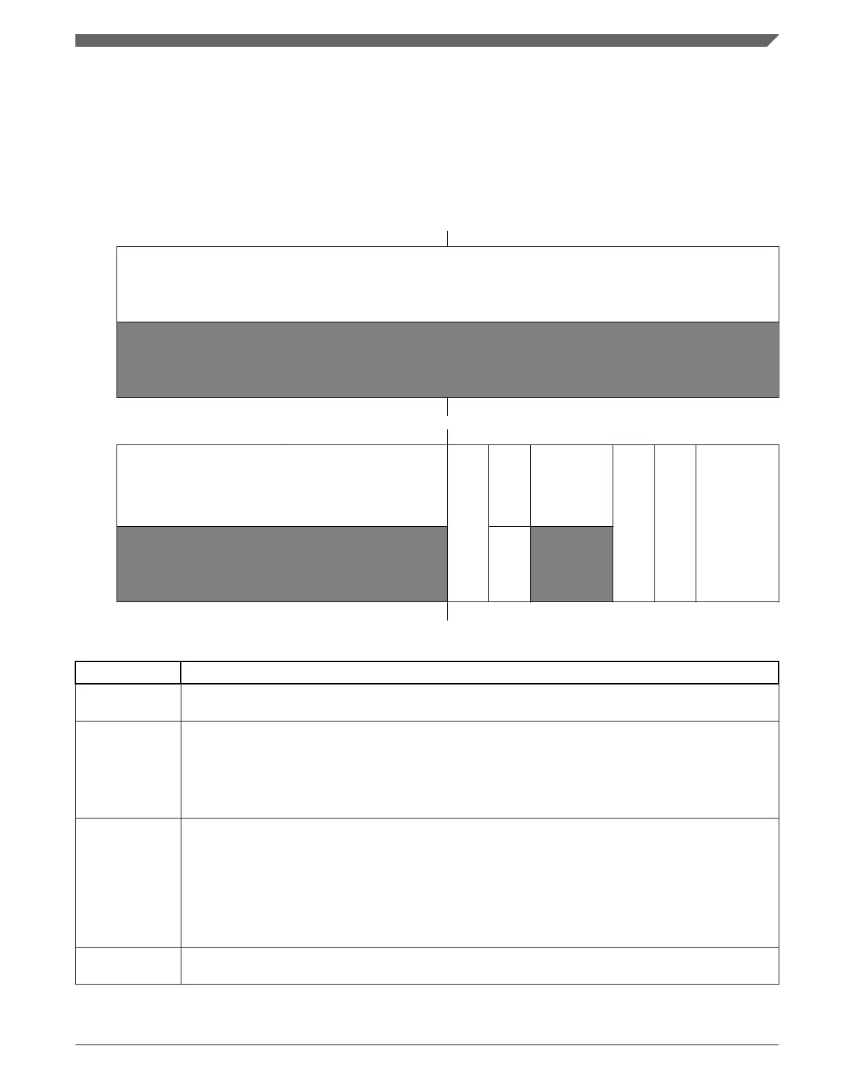
34.3.7 Status and Control Register 3 (ADCx_SC3)
The Status and Control Register 3 (SC3) controls the calibration, continuous convert, and
hardware averaging functions of the ADC module.
Address: Base address + 24h offset
Bit 31 30 29 28 27 26 25 24 23 22 21 20 19 18 17 16
R
0
W
Reset
0 0 0 0 0 0 0 0 0 0 0 0 0 0 0 0
Bit
15 14 13 12 11 10 9 8 7 6 5 4 3 2 1 0
R
0
CAL
CALF
0
ADCO
AVGE
AVGS
W
w1c
Reset
0 0 0 0 0 0 0 0 0 0 0 0 0 0 0 0
ADCx_SC3 field descriptions
Field Description
31–8
Reserved
This field is reserved.
This read-only field is reserved and always has the value 0.
7
CAL
Calibration
Begins the calibration sequence when set. This field stays set while the calibration is in progress and is
cleared when the calibration sequence is completed. CALF must be checked to determine the result of the
calibration sequence. Once started, the calibration routine cannot be interrupted by writes to the ADC
registers or the results will be invalid and CALF will set. Setting CAL will abort any current conversion.
6
CALF
Calibration Failed Flag
Displays the result of the calibration sequence. The calibration sequence will fail if SC2[ADTRG] = 1, any
ADC register is written, or any stop mode is entered before the calibration sequence completes. Writing 1
to CALF clears it.
0 Calibration completed normally.
1 Calibration failed. ADC accuracy specifications are not guaranteed.
5–4
Reserved
This field is reserved.
This read-only field is reserved and always has the value 0.
Table continues on the next page...
Chapter 34 Analog-to-Digital Converter (ADC)
K22F Sub-Family Reference Manual, Rev. 4, 08/2016
NXP Semiconductors 779

 Loading...