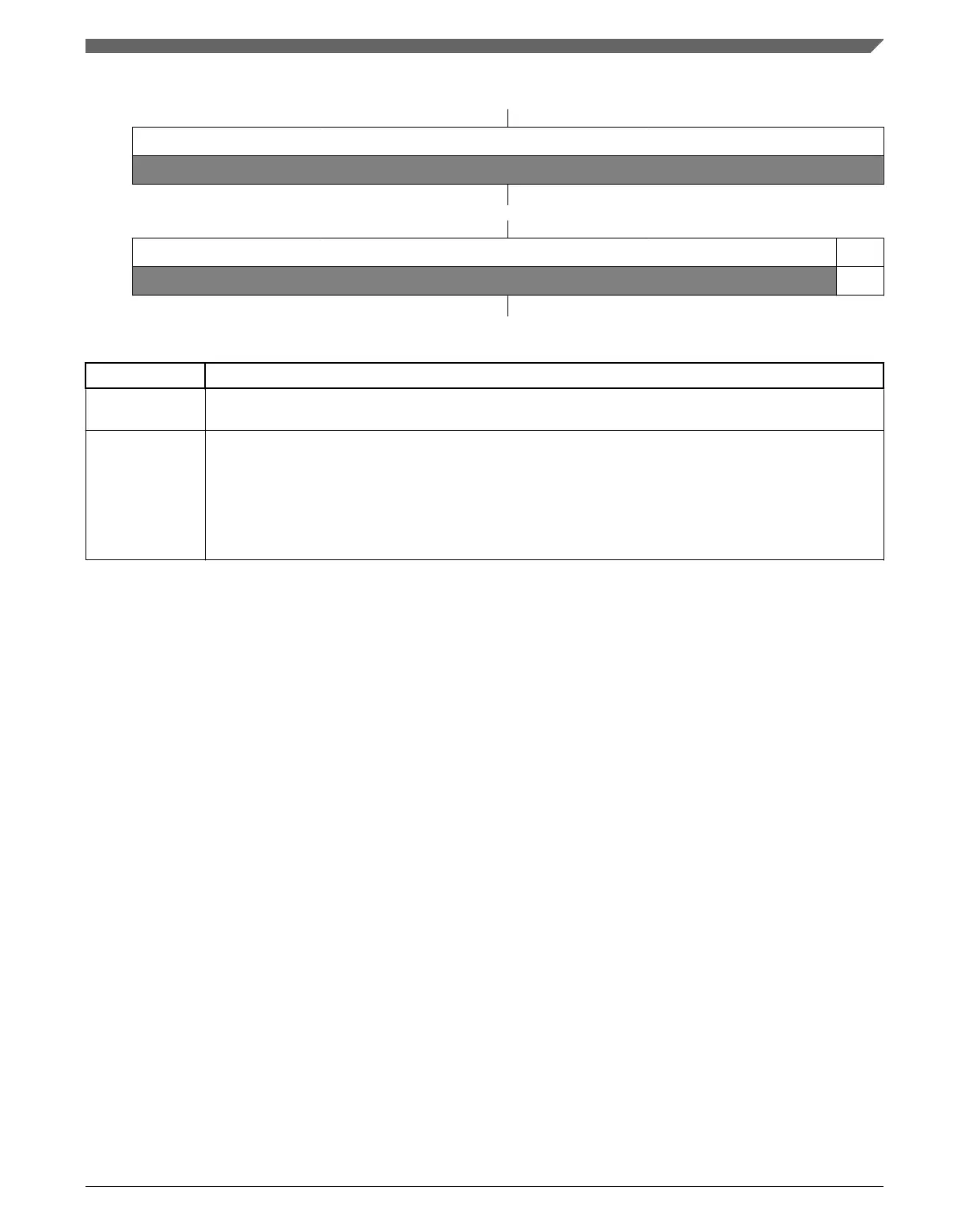
Address: 4003_7000h base + 10Ch offset + (16d × i), where i=0d to 3d
Bit 31 30 29 28 27 26 25 24 23 22 21 20 19 18 17 16
R
0
W
Reset
0 0 0 0 0 0 0 0 0 0 0 0 0 0 0 0
Bit
15 14 13 12 11 10 9 8 7 6 5 4 3 2 1 0
R
0 TIF
W
w1c
Reset
0 0 0 0 0 0 0 0 0 0 0 0 0 0 0 0
PIT_TFLGn field descriptions
Field Description
31–1
Reserved
This field is reserved.
This read-only field is reserved and always has the value 0.
0
TIF
Timer Interrupt Flag
Sets to 1 at the end of the timer period. Writing 1 to this flag clears it. Writing 0 has no effect. If enabled,
or, when TCTRLn[TIE] = 1, TIF causes an interrupt request.
0 Timeout has not yet occurred.
1 Timeout has occurred.
40.4 Functional description
This section provides the functional description of the module.
40.4.1
General operation
This section gives detailed information on the internal operation of the module. Each
timer can be used to generate trigger pulses and interrupts. Each interrupt is available on
a separate interrupt line.
40.4.1.1
Timers
The timers generate triggers at periodic intervals, when enabled. The timers load the start
values as specified in their LDVAL registers, count down to 0 and then load the
respective start value again. Each time a timer reaches 0, it will generate a trigger pulse
and set the interrupt flag.
All interrupts can be enabled or masked by setting TCTRLn[TIE]. A new interrupt can be
generated only after the previous one is cleared.
Chapter 40 Periodic Interrupt Timer (PIT)
K22F Sub-Family Reference Manual, Rev. 4, 08/2016
NXP Semiconductors 1035

 Loading...