Refer to signal multiplexing information for this MCU for more details.
Table 26-1. OSC Signal Descriptions
Signal Description I/O
EXTAL External clock/Oscillator input I
XTAL Oscillator output O
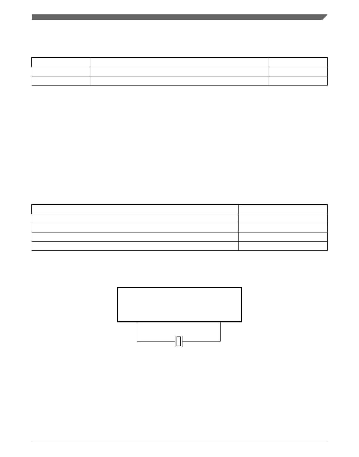
26.5 External Crystal / Resonator Connections
The connections for a crystal/resonator frequency reference are shown in the figures
found here.
When using low-frequency, low-power mode, the only external component is the crystal
or ceramic resonator itself. In the other oscillator modes, load capacitors (C
x
, C
y
) and
feedback resistor (R
F
) are required. The following table shows all possible connections.
Table 26-2. External Caystal/Resonator Connections
Oscillator Mode Connections
Low-frequency (32 kHz), low-power Connection 1
Low-frequency (32 kHz), high-gain Connection 2/Connection 3
1
High-frequency (3~32 MHz), low-power Connection 1/Connection 3
2,2
High-frequency (3~32 MHz), high-gain Connection 2/Connection 3
2
1. When the load capacitors (Cx, Cy) are greater than 30 pF, use Connection 3.
2. With the low-power mode, the oscillator has the internal feedback resistor R
F
. Therefore, the feedback resistor must not be
externally with the Connection 3.
OSC
EXTAL
Crystal or Resonator
VSS
XTAL
Figure 26-2. Crystal/Ceramic Resonator Connections - Connection 1
Chapter 26 Oscillator (OSC)
K22F Sub-Family Reference Manual, Rev. 4, 08/2016
NXP Semiconductors 579

 Loading...