50.2.5 Port Data Input Register (GPIOx_PDIR)
NOTE
Do not modify pin configuration registers associated with pins
not available in your selected package. All unbonded pins not
available in your package will default to DISABLE state for
lowest power consumption.
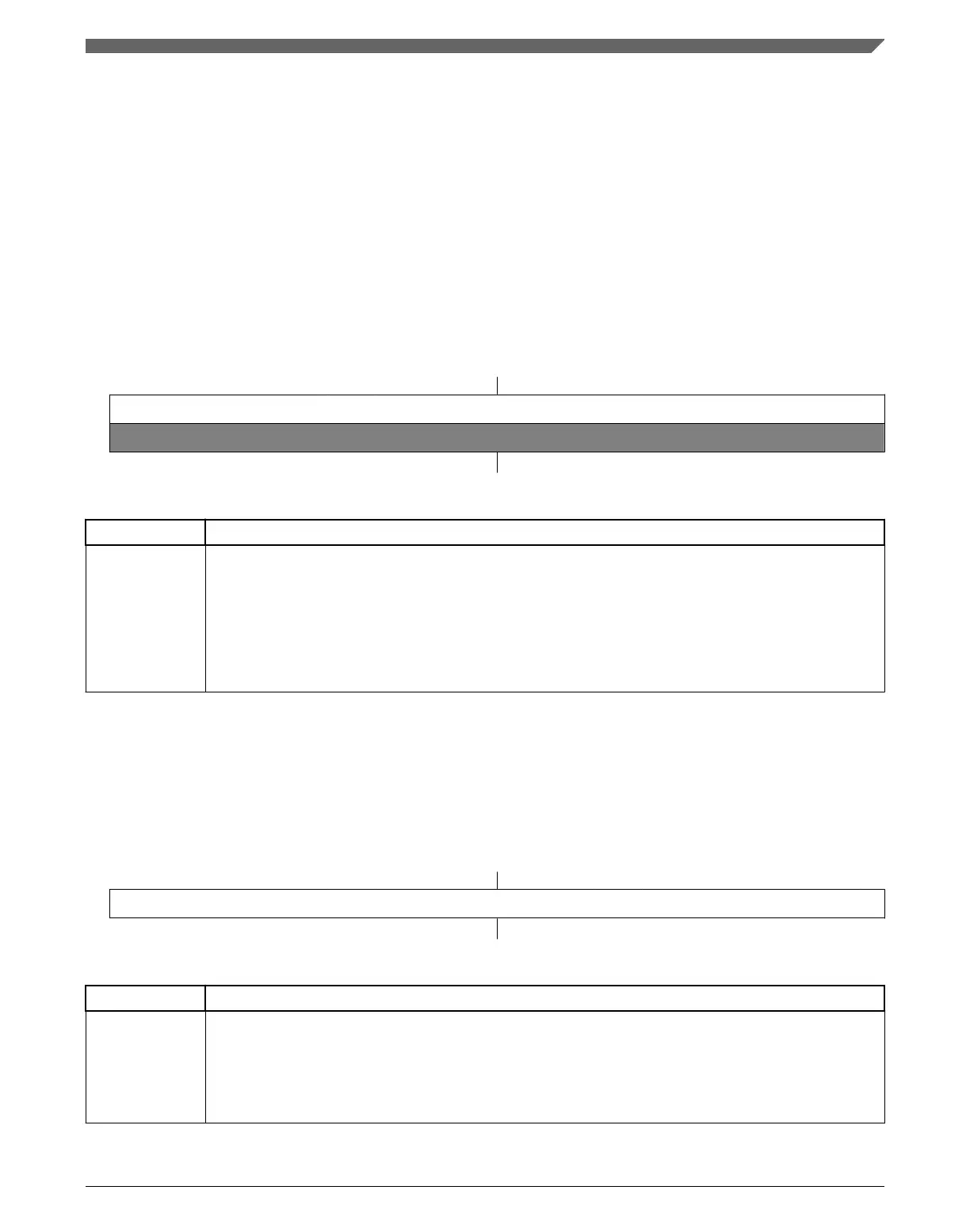
Address:
Base address + 10h offset
Bit 31 30 29 28 27 26 25 24 23 22 21 20 19 18 17 16 15 14 13 12 11 10 9 8 7 6 5 4 3 2 1 0
R
PDI
W
Reset
0 0 0 0 0 0 0 0 0 0 0 0 0 0 0 0 0 0 0 0 0 0 0 0 0 0 0 0 0 0 0 0
GPIOx_PDIR field descriptions
Field Description
PDI Port Data Input
Reads 0 at the unimplemented pins for a particular device. Pins that are not configured for a digital
function read 0. If the Port Control and Interrupt module is disabled, then the corresponding bit in PDIR
does not update.
0 Pin logic level is logic 0, or is not configured for use by digital function.
1 Pin logic level is logic 1.
50.2.6 Port Data Direction Register (GPIOx_PDDR)
The PDDR configures the individual port pins for input or output.
Address:
Base address + 14h offset
Bit 31 30 29 28 27 26 25 24 23 22 21 20 19 18 17 16 15 14 13 12 11 10 9 8 7 6 5 4 3 2 1 0
R
PDD
W
Reset
0 0 0 0 0 0 0 0 0 0 0 0 0 0 0 0 0 0 0 0 0 0 0 0 0 0 0 0 0 0 0 0
GPIOx_PDDR field descriptions
Field Description
PDD Port Data Direction
Configures individual port pins for input or output.
0 Pin is configured as general-purpose input, for the GPIO function.
1 Pin is configured as general-purpose output, for the GPIO function.
Chapter 50 General-Purpose Input/Output (GPIO)
K22F Sub-Family Reference Manual, Rev. 4, 08/2016
NXP Semiconductors 1381

 Loading...