3.3.6.1 Crossbar-Light Switch Master Assignments
The masters connected to the crossbar switch are assigned as follows:
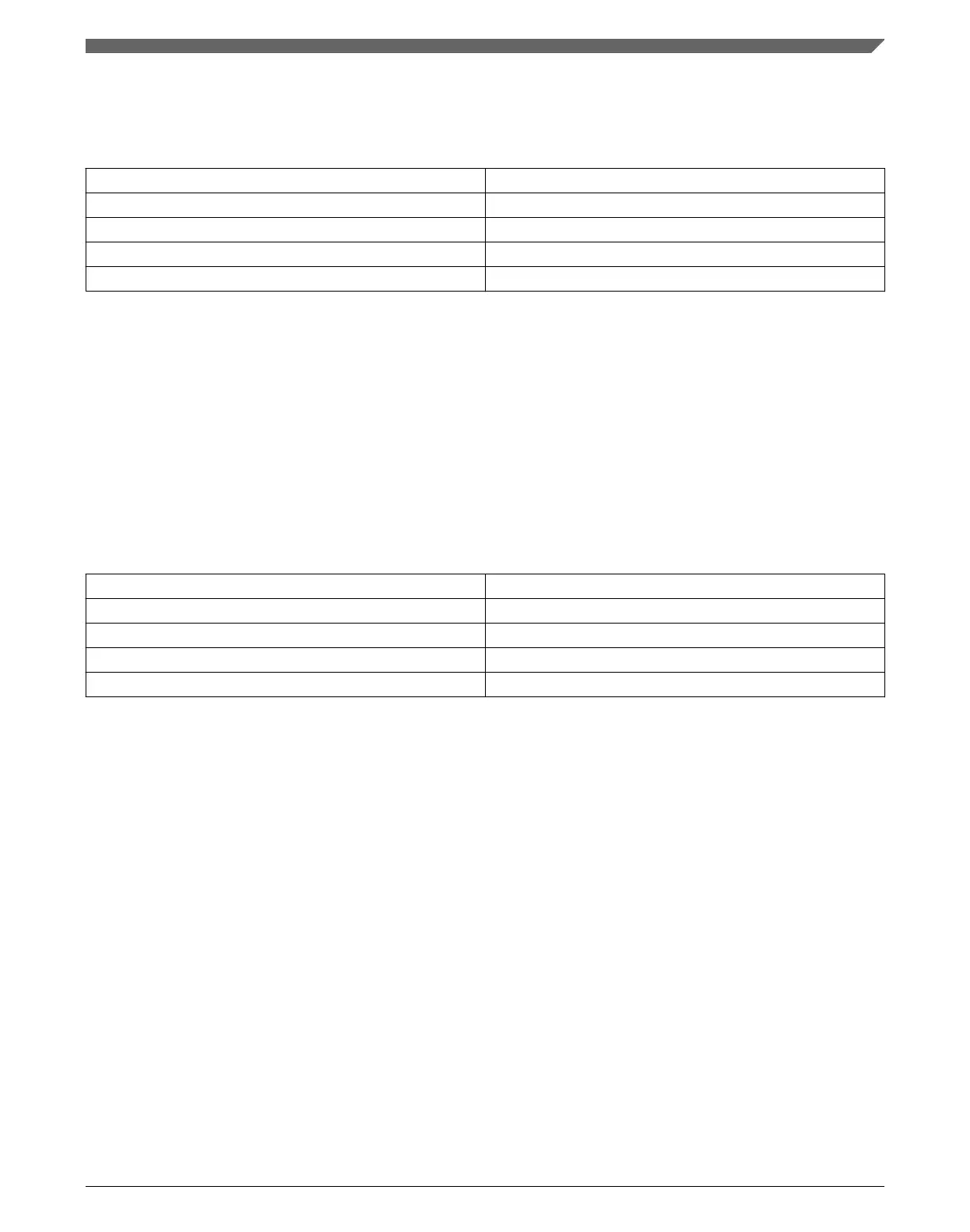
Master module Master port number
ARM core code bus 0
ARM core system bus 1
DMA /EzPort 2
USB OTG 4
NOTE
The DMA and EzPort share a master port. Since these modules
never operate at the same time, no configuration or arbitration
explanations are necessary.
3.3.6.2 Crossbar-Light Switch Slave Assignments
The slaves connected to the crossbar switch are assigned as follows:
Slave module Slave port number
Flash memory controller 0
SRAM controllers 1,2
Peripheral bridge 0/GPIO
1
3
FlexBus 4
1. See System memory map for access restrictions.
3.3.7 Peripheral Bridge Configuration
This section summarizes how the module has been configured in the chip. For a
comprehensive description of the module itself, see the module’s dedicated chapter.
Chapter 3 Chip Configuration
K22F Sub-Family Reference Manual, Rev. 4, 08/2016
NXP Semiconductors 73

 Loading...