FTMx_OUTMASK field descriptions (continued)
Field Description
0 Channel output is not masked. It continues to operate normally.
1 Channel output is masked. It is forced to its inactive state.
2
CH2OM
Channel 2 Output Mask
Defines if the channel output is masked or unmasked.
0 Channel output is not masked. It continues to operate normally.
1 Channel output is masked. It is forced to its inactive state.
1
CH1OM
Channel 1 Output Mask
Defines if the channel output is masked or unmasked.
0 Channel output is not masked. It continues to operate normally.
1 Channel output is masked. It is forced to its inactive state.
0
CH0OM
Channel 0 Output Mask
Defines if the channel output is masked or unmasked.
0 Channel output is not masked. It continues to operate normally.
1 Channel output is masked. It is forced to its inactive state.
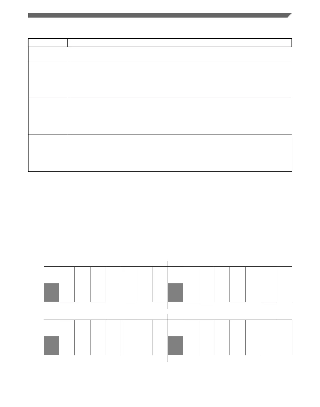
39.3.14 Function For Linked Channels (FTMx_COMBINE)
This register contains the control bits used to configure the fault control, synchronization,
deadtime insertion, Dual Edge Capture mode, Complementary, and Combine mode for
each pair of channels (n) and (n+1), where n equals 0, 2, 4, and 6.
Address:
Base address + 64h offset
Bit 31 30 29 28 27 26 25 24 23 22 21 20 19 18 17 16
R
0
FAULTEN3
SYNCEN3
DTEN3
DECAP3
DECAPEN3
COMP3
COMBINE3
0
FAULTEN2
SYNCEN2
DTEN2
DECAP2
DECAPEN2
COMP2
COMBINE2
W
Reset
0 0 0 0 0 0 0 0 0 0 0 0 0 0 0 0
Bit
15 14 13 12 11 10 9 8 7 6 5 4 3 2 1 0
R
0
FAULTEN1
SYNCEN1
DTEN1
DECAP1
DECAPEN1
COMP1
COMBINE1
0
FAULTEN0
SYNCEN0
DTEN0
DECAP0
DECAPEN0
COMP0
COMBINE0
W
Reset
0 0 0 0 0 0 0 0 0 0 0 0 0 0 0 0
Chapter 39 FlexTimer Module (FTM)
K22F Sub-Family Reference Manual, Rev. 4, 08/2016
NXP Semiconductors 919

 Loading...