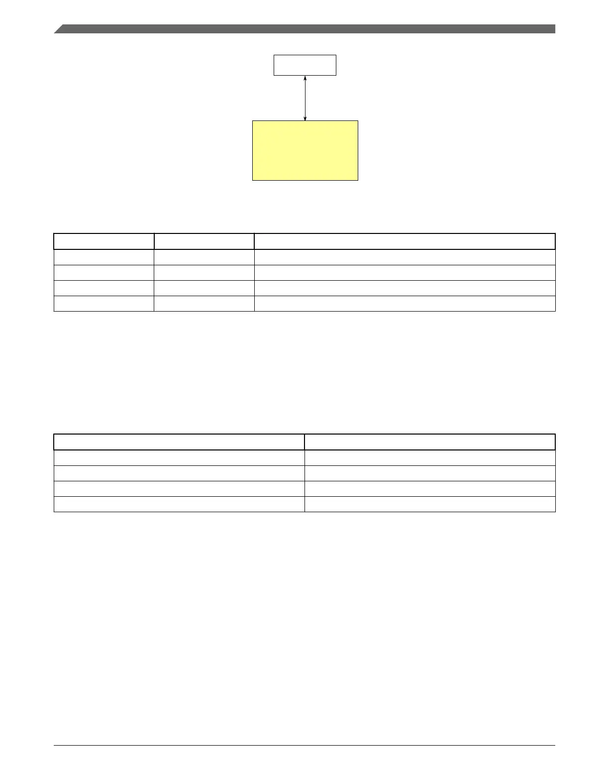
Register
access
Peripheral
bridge
Periodic interrupt
timer
Figure 3-42. PIT configuration
Table 3-56. Reference links to related information
Topic Related module Reference
Full description PIT PIT
System memory map System memory map
Clocking Clock Distribution
Power management Power management
3.8.3.1 PIT/DMA Periodic Trigger Assignments
The PIT generates periodic trigger events to the DMA Mux as shown in the table below.
Table 3-57. PIT channel assignments for periodic DMA triggering
DMA Channel Number PIT Channel
DMA Channel 0 PIT Channel 0
DMA Channel 1 PIT Channel 1
DMA Channel 2 PIT Channel 2
DMA Channel 3 PIT Channel 3
3.8.3.2 PIT/ADC Triggers
PIT triggers are selected as ADCx trigger sources using the
SIM_SOPT7[ADCxTRGSEL] fields. For more details, refer to SIM chapter.
3.8.4
Low-power timer configuration
This section summarizes how the module has been configured in the chip. For a
comprehensive description of the module itself, see the module’s dedicated chapter.
Timers
K22F Sub-Family Reference Manual, Rev. 4, 08/2016
118 NXP Semiconductors

 Loading...