17.1.2.4 Debug mode
When the chip is in Debug mode and then enters LLS or a VLLSx mode, no debug logic
works in the fully-functional low-leakage mode. Upon an exit from the LLS or VLLSx
mode, the LLWU becomes inactive.
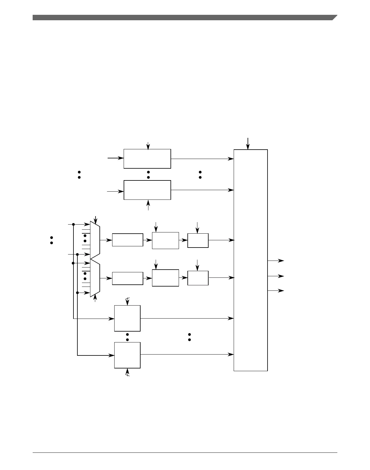
17.1.3 Block diagram
The following figure is the block diagram for the LLWU module.
Module0 interrupt flag
(LLWU_M0IF)
WUME0
LLWU_MWUF0 occurred
Internal
module
sources
LLWU
controller
External
pin sources
exit low leakge mode
interrupt flow
reset flow
LLWU_P0
LLWU_P15
Pin filter 1
wakeup
occurred
Interrupt module
flag detect
WUPE15
2
Edge
detect
enter low leakge mode
WUPE0
Edge
detect
Module7 interrupt flag
(LLWU_M7IF)
WUME7
LLWU_MWUF7 occurred
Interrupt module
flag detect
LPO
Pin filter 2
LPO
FILT1[FILTE]
Pin filter 1
Synchronizer
Synchronizer
Edge
detect
LLWU_P15
wakeup occurred
Edge
detect
Pin filter 2
wakeup
occurred
2
LLWU_P0
wakeup occurred
FILT2[FILTSEL]
FILT1[FILTSEL]
FILT2[FILTE]
Figure 17-1. LLWU block diagram
Chapter 17 Low-Leakage Wakeup Unit (LLWU)
K22F Sub-Family Reference Manual, Rev. 4, 08/2016
NXP Semiconductors 381

 Loading...